
Wiring substrate and method for producing the same

a technology of wiring conductors and substrates, applied in the direction of resistive material coating, metallic pattern materials, solid-state devices, etc., can solve the problems of plated metal layer harming the human body, difficult to form leads for plating, and inability to uniformly and firmly precipitate elements of group 1b on the surface of wiring conductors for coating

Inactive Publication Date: 2005-04-21
KYOCERA CORP
View PDF2 Cites 10 Cited by
  • Summary
  • Abstract
  • Description
  • Claims
  • Application Information

AI Technical Summary

Benefits of technology

[0020] The invention is devised to solve the problems, and an object of the invention is to provide a wiring substrate in which a wiring conductor is coated with an electroless plated metal layer uniformly and firmly, and the plated metal layer is free from lead so that the problem of a spotted color change is not caused, and the human body is not harmed.
[0026] According to the invention, the electroless plated metal layer coating the wiring conductor contains an element of Group 1B that is necessary to form a coating of the electroless plated metal layer, but does not contain lead. Therefore, the function of the element of Group 1B provides the wiring conductor with satisfactory catalytic activity, so that only the wiring conductor is coated with the electroless plated-metal layer uniformly, and the problems of a spotted color change of the plated metal layer caused by the lead contained in the plated metal layer and the harm to the human body can be prevented effectively.
[0037] According to the invention, the electroless plated metal layer coating the wiring conductor contains a platinum group metal that is necessary to form a coating of the electroless plated metal layer, but does not contain lead. Therefore, the function of the platinum group metal provides the wiring conductor with satisfactory catalytic activity, so that only the wiring conductor is coated with the electroless plated metal layer uniformly, and the problems of a spotted color change of the plated metal layer caused by the lead contained in the plated metal layer and the harm to the human body can be prevented effectively.

Problems solved by technology

As a method for forming a coating of a plated metal layer such as nickel, electroless plating, which does not require leads, has come to be used more commonly, because higher density of the wiring conductors resulting from compactness of the wiring substrate makes it difficult to form leads for supplying power for plating.
The conventional wiring substrate contains lead in the plated metal layer, as described above, so that when heat is applied to the plated metal layer, the lead moves and is diffused onto the surface of the plated metal layer and oxidized there, which causes a functional problem that the color is changed spottedly and environmental and security problems that the lead in the plated metal layer harms the human body.
However, in this case, since the surface of the wiring conductor made of a metal having a high melting point is not sufficiently sensitive to the precipitation and the coating of elements of Group 1B such as copper or platinum group metals such as palladium or platinum, the elements of Group 1B cannot be precipitated on the surfaces of the wiring conductors uniformly and firmly for coating.
As a result, roughness, cracks, swelling or the like may be generated.

Method used


Image

  • Wiring substrate and method for producing the same
  • Wiring substrate and method for producing the same
  • Wiring substrate and method for producing the same

Examples


first embodiment

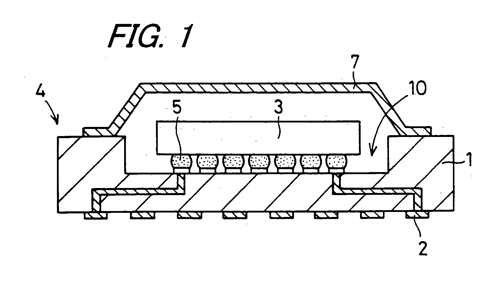
[0050]FIG. 1 is a sectional view showing an example of a wiring substrate of the invention that is applied to a semiconductor element accommodation package for accommodating a semiconductor element. Reference numeral 1 denotes an insulator, and reference numeral 2 is a wiring conductor. The insulator 1 and the wiring conductor 2 constitute a wiring substrate 4 for mounting a semiconductor element 3.

[0051] The insulator 1 is made of an electrically insulating material such as an aluminum oxide sintered body, an aluminum nitride sintered body, a mullite sintered body, or silicon carbide sintered body, and has a mounting portion for mounting the semiconductor element 3 on its upper surface. The wiring conductor 2 made of a metal having a high melting point such as tungsten, molybdenum, manganese and other various metals is formed on the insulator 1 from the mounting portion on which the semiconductor element 3 is to be mounted to the lower surface thereof.

[0052] In the insulator 1, th...

second embodiment

[0073] Next, a wiring substrate of the invention will be described.

[0074] In this embodiment, the components corresponding to those in the structure of the first embodiment bear the same reference numeral, and the description thereof will be omitted.

[0075] In this embodiment, the structure of the wiring substrate is similar to that of the first embodiment, and the aspect to be noted is that the electroless plated metal layer contains a platinum group metal and is free from lead.

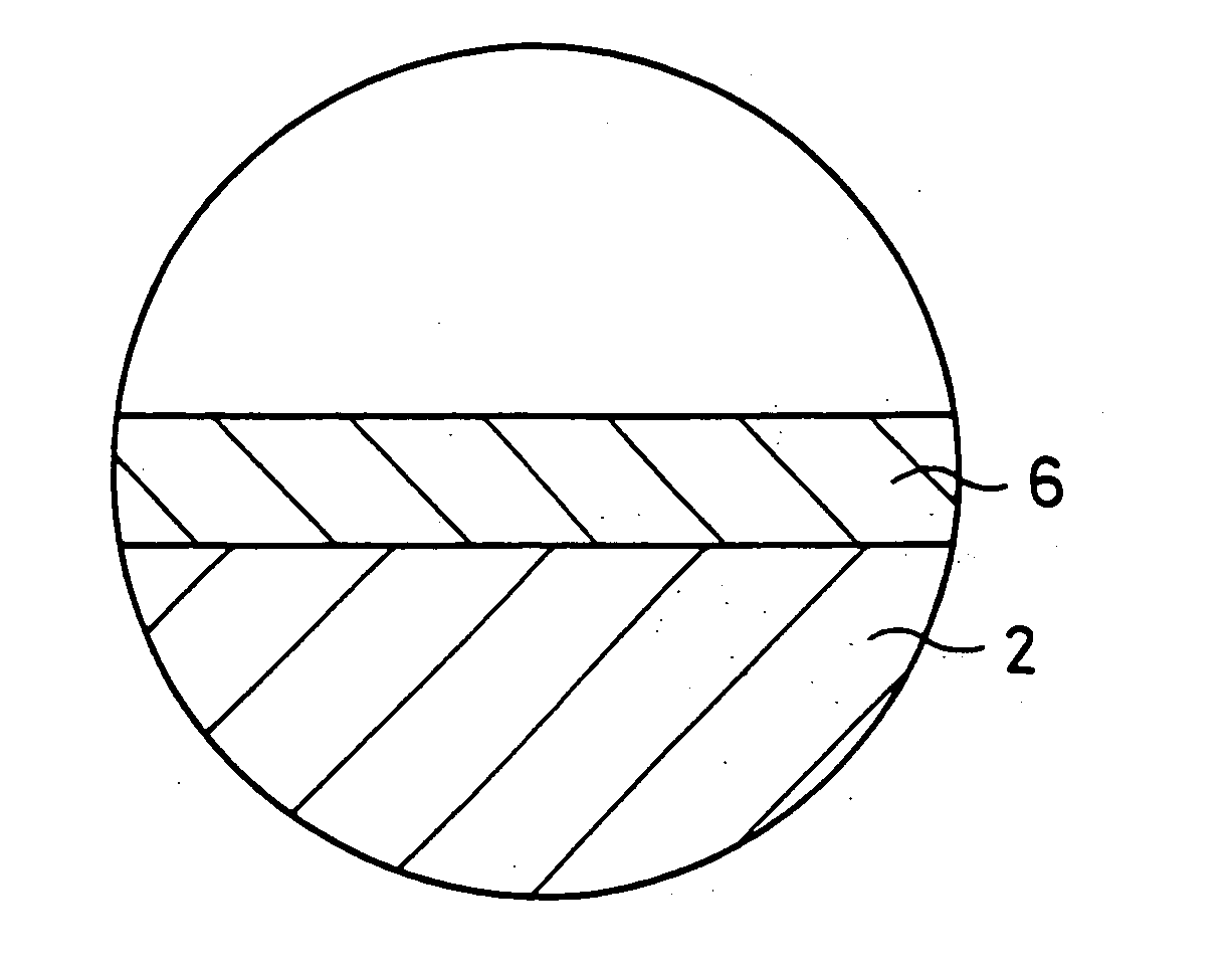
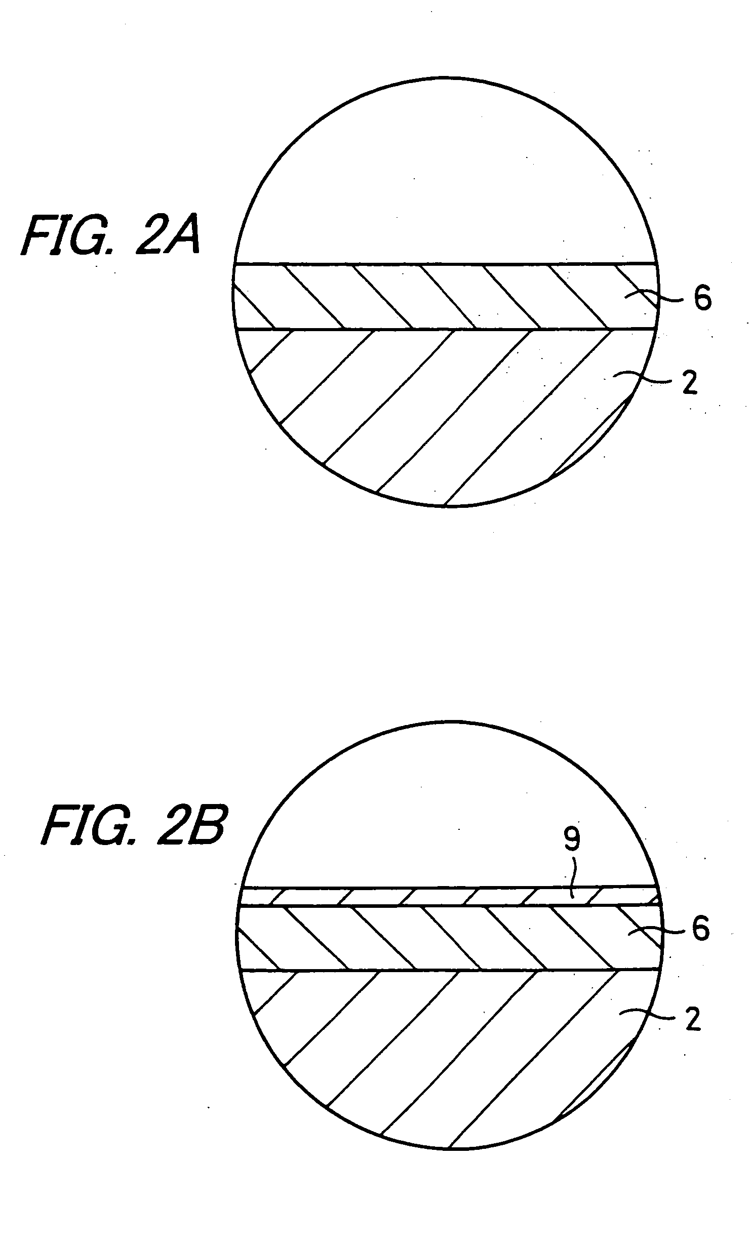
[0076]FIG. 4A is an enlarged sectional view showing an enlarged part of the wiring substrate of the second embodiment of the invention. The surface of the wiring conductor 2 is coated with the plated metal layer 16 by electroless plating, as shown in the sectional view of FIG. 4A.

[0077] The plated metal layer 16 serves to improve the wettability, the joining strength, and the bonding properties of solders with respect to the wiring conductor 2 and is made of a high purity nickel that contains nickel in a c...


PUM

PropertyMeasurementUnit
thicknessaaaaaaaaaa
thicknessaaaaaaaaaa
thicknessaaaaaaaaaa

Abstract

An object of the invention is to prevent the color on a surface of a plated metal layer from changing. The invention is a wiring substrate obtained by forming a wiring conductor made of a metal having a high melting point on an insulator, and coating a surface of the wiring conductor with an electroless plated metal layer, wherein the electroless plated metal layer contains an element of Group 1B and is free from lead.

Description

BACKGROUND OF THE INVENTION [0001] 1. Field of the Invention [0002] The present invention relates to a wiring substrate on which an electronic component such as a semiconductor element, a capacitive element, a resistor or the like is mounted, and that includes a wiring conductor on its surface, the wiring conductor being coated with a plated metal layer by electroless plating. The invention also relates to a method for producing the same. [0003] 2. Description of the Related Art [0004] Conventionally, a wiring substrate on which an electronic component such as a semiconductor element, a capacitive element, a resistor or the like is to be mounted generally includes a substantially rectangular plate-shaped insulator and a plurality of wiring conductors. The insulator is made of an aluminum oxide sintered body and has a mounting portion for mounting an electronic component. The plurality of wiring conductors are made of a metal material having a high melting point such as tungsten, mol...

Claims


Application Information

Patent Timeline
Patent Type & Authority Applications(United States)
IPC IPC(8): H05K1/09C23C18/18H01L21/48H01L23/498H05K3/18H05K3/24
CPCH01L21/4846H01L23/49866H01L2924/15174H05K1/092Y10T428/24917H01L2224/16225H01L2924/16152Y10T428/24926H05K3/246H01L2924/00014H01L2224/0401
Inventor HOSOI, YOSHIHIROFUKUDA, YASUO
Owner KYOCERA CORP
Learn More