Membrane/distillation method and system for extracting CO2 from hydrocarbon gas

a hydrocarbon gas and membrane technology, applied in the field of membrane/distillation method and system for extracting co2 from hydrocarbon gas, can solve the problems of unsuitable pipeline carrier, unsuitable for use as fuel, unacceptably high carbon dioxide content of natural gas, etc., and achieve the effect of reducing hydrocarbon losses and improving performan

Active Publication Date: 2005-05-05
NAT TANK
View PDF13 Cites 47 Cited by
  • Summary
  • Abstract
  • Description
  • Claims
  • Application Information

AI Technical Summary

Benefits of technology

[0023] The membrane system has at least one membrane unit. The membrane system can have a plurality of membrane units. Often, the plurality of membrane units are arranged in a series configuration. The series configuration leads to improved performance when the membrane module performance is less than predictions based on an ideal membrane unit. A recycle configuration of the membrane modules can also be used to reduce hydroc

Problems solved by technology

Much of the world's natural gas supply is contaminated with unacceptably high levels of carbon dioxide (CO2).
In some cases, in addition to excessive CO2, the natural gas may also contain excessive levels of sulfur compounds.
In many cases, the carbon dioxide a

Method used


Image

  • Membrane/distillation method and system for extracting CO2 from hydrocarbon gas
  • Membrane/distillation method and system for extracting CO2 from hydrocarbon gas
  • Membrane/distillation method and system for extracting CO2 from hydrocarbon gas

Examples


Embodiment Construction

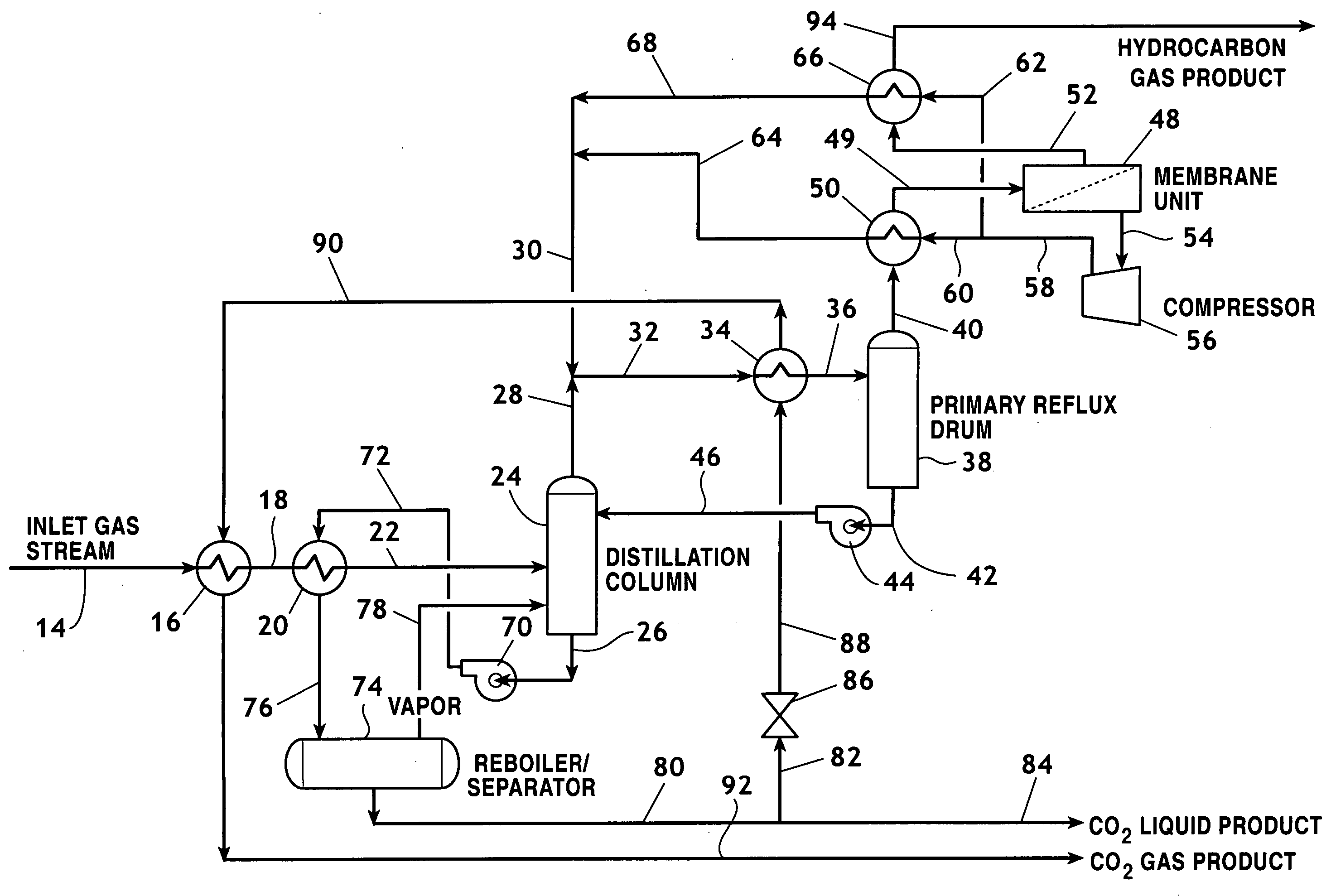
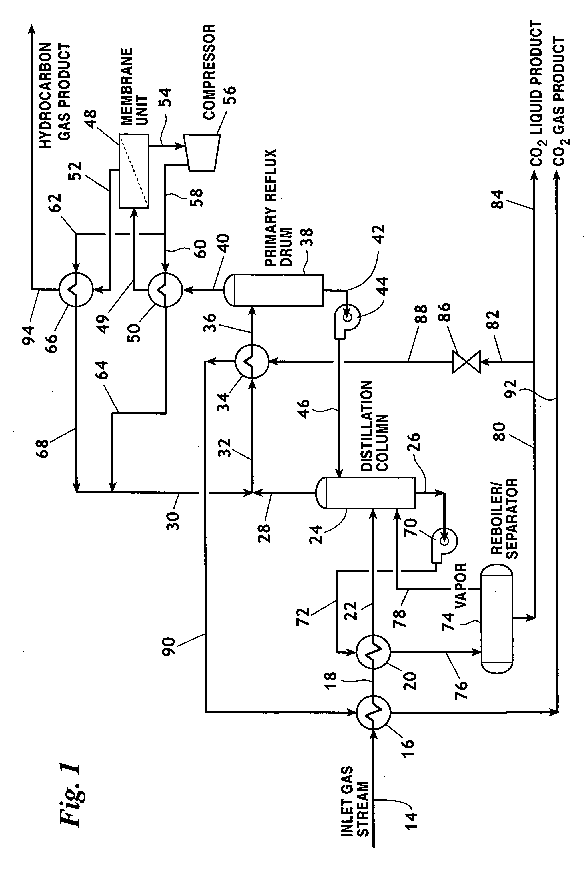
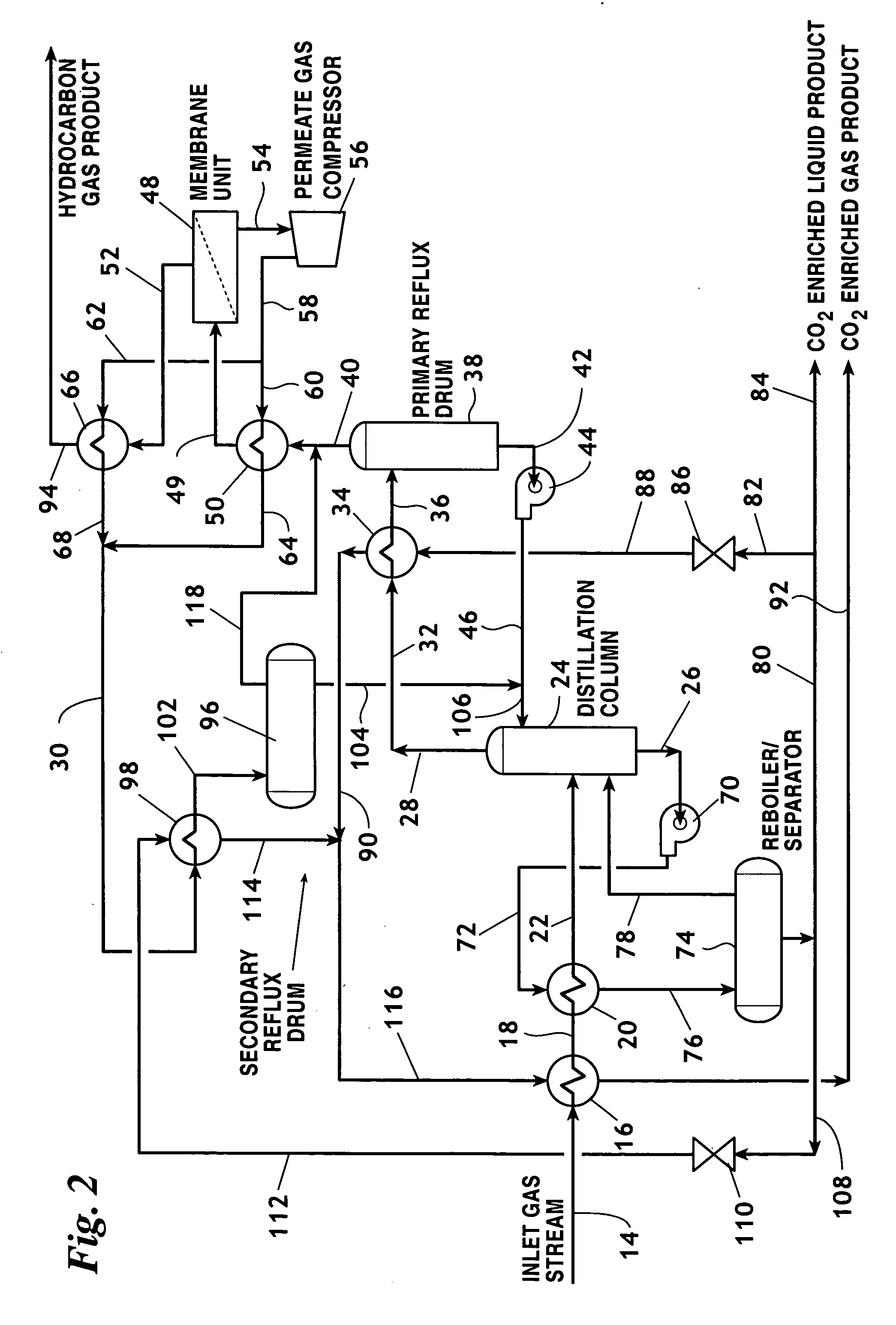
[0028] Major elements of the invention are indicated in the drawings by numerals as follows:

14Inlet gas stream16Inlet cross heat exchanger18Cooled inlet stream20Reboiler cross heater22Conditioned inlet stream24Distillation column26CO2 bottom product stream28Distillation overhead stream30Permeate stream32Combined condenser inlet stream34Primary condenser36Primary condenser outlet stream38Primary reflux drum40Hydrocarbon vapor stream42Primary reflux liquid stream44Primary reflux pump46Pumped primary reflux liquid stream48Membrane unit49Membrane inlet50Permeate cross heat exchanger52Hydrocarbon gas product stream54Permeate stream56Compressor58Compressed permeate stream60First permeate cross heat exchanger feed stream62Second permeate cross heat exchanger feed stream64Permeate cross heat exchanger outlet stream66Hydrocarbon product cross heat exchanger68Hydrocarbon product cross heat exchanger outlet stream70CO2 bottom product pump72Pumped CO2 bottom product stream74Reboil / separator76...


PUM


Abstract

A method of separating CO2 from a hydrocarbon gas inlet stream that is within predetermined pressure and temperature ranges, including the steps of subjecting the inlet stream to fractional distillation providing a CO2 bottom product stream and a distillation overhead stream, passing the distillation overhead stream to the inlet of a primary reflux drum producing a primary reflux liquid stream and a hydrocarbon vapor stream, subjecting the hydrocarbon vapor stream to membrane separation to provide a hydrocarbon product stream and a permeate stream, compressing the permeate stream and recycling the compressed permeate stream to the inlet of the primary reflux drum thereby providing a CO2 liquid product and a hydrocarbon gas product.

Description

REFERENCE TO PENDING APPLICATIONS [0001] This application is not based upon any pending domestic or international patent application. REFERENCE TO MICROFICHE APPENDIX [0002] This application is not referenced in any microfiche appendix. FIELD OF THE INVENTION [0003] The present invention relates to a method and system for treating a hydrocarbon mixture to remove CO2 along with attendant sulfur compounds using distillation and membrane separation systems with critically arranged distillation reflux paths. BACKGROUND OF THE INVENTION [0004] Much of the world's natural gas supply is contaminated with unacceptably high levels of carbon dioxide (CO2). In some cases, in addition to excessive CO2, the natural gas may also contain excessive levels of sulfur compounds. Such sulfur compounds include hydrogen sulfide and carbonyl sulfide. In many cases, the carbon dioxide and sulfur contaminants lower the BTU value of natural gas making such gas unsuitable for use as a fuel or unsuitable to be...

Claims


Application Information

Patent Timeline
IPC IPC(8): B01D53/22C10L3/10F25J3/02
CPCB01D53/229Y10S62/929F25J3/0209F25J3/0233F25J3/0266F25J2200/02F25J2200/74F25J2200/76F25J2205/40F25J2205/80F25J2230/08F25J2235/80F25J2245/02F25J2270/02Y02C10/10Y02C10/12F25J2215/04C10L3/10Y02C20/40
Inventor PARRO, DAVID L.SANDERS, EDGAR S. JR.
Owner NAT TANK
Why Eureka
Try Eureka