Variable valve train apparatus for an internal combustion engine

a technology of variable valve train and internal combustion engine, which is applied in mechanical equipment, valve arrangements, machines/engines, etc., can solve the problems of reducing the durability and reliability of the variable valve train apparatus, and affecting the operation of the valve train. , to achieve the effect of reducing the endurance avoiding deviating wear of the operating portion, and increasing the width of the operating portion

Active Publication Date: 2005-05-12
MITSUBISHI MOTORS CORP
View PDF1 Cites 1 Cited by
  • Summary
  • Abstract
  • Description
  • Claims
  • Application Information

AI Technical Summary

Benefits of technology

[0033] The object of this invention is to provide a variable valve train apparatus for an internal combustion engine, which is capable of preventing a high-speed rocker arm from being inclined when receiving a driving force from a cam, thereby avoiding various disadvantages due to a deviated load on an operating portion thereof (a sliding portion with the cam), and capable of eliminating the need of increasing the width of the operating portion to thereby reduce the inertia mass of the high-speed rocker arm, making it possible to realize an accurate opening and closing characteristic of intake and exhaust valves.
[0037] This reduces misalignment of the second cam and the operating portion due to the inclination of the second rocker arm. Hence, the operating portion is held in normal contact with the second cam, and thus receives substantially uniform load in the longitudinal direction. As a result, it is unnecessary to increase the width of the operating portion as a countermeasure to avoid deviated wear of the operating portion and the second cam, reduction in endurance of the operating portion, etc. Accordingly, the inertia mass of the second rocker arm can be reduced.
[0038] As explained above, according to the variable valve train apparatus of this invention, the inclination of the second rocker arm which would otherwise be caused when it receives the driving force from the side of the second cam is prevented, thereby eliminating various problems due to the deviated load on the operating portion, and makes it unnecessary to increase the width of the operating portion to reduce the inertia mass of the second rocker arm, whereby accurate opening and closing characteristics of the intake and exhaust valves can be realized.

Problems solved by technology

This poses a problem that the opening and closing characteristic of the valve train is worsened, especially, in a high-speed rotation region.
This problem is especially noticeable in a rocker arm provided with a roller, but a similar problem is caused also in a rocker arm using a slipper instead of a roller.
The deviated load on the bearing increases wear and friction, and by extension disadvantageously lowers the durability and reliability of the variable valve train apparatus.
Accordingly, there periodically occurs undesired bending and torsion in the vicinity of the driving-force transmission point 208 of the low-speed rocker arm 202 each time the driving force is transmitted from the high-speed rocker arm 203, resulting in a problem of deteriorating the opening and closing characteristic of the intake valve in the high-speed rotation region or the like.
This is disadvantageous in strength and rigidity.
This causes a valve jump and bounce especially in high-speed rotation region, posing a problem that the opening and closing characteristic of the valve train is worsened.
Particularly in a case where the variable valve train apparatus shown in FIG. 20 is mounted to both the intake and exhaust sides of a single camshaft, these variable valve train apparatuses occupy a space right above a combustion chamber to make it difficult to ensure an installation space for a spark plug, posing a problem that the layout of the spark plug, etc. is limited.
This is one of the causes of lowering the opening and closing characteristic of the valve train in a high-speed rotation region.
Therefore, even when the valve clearance on the side of the low-speed cam is adjusted to the normal one by means of the adjustment bolt 411 provided in the intake valve 405, this does not guarantee that an equivalent valve clearance can also be attained on the side of the high-speed cam.
The same result is caused when a vertical angular error a in the axis Lc is produced due to misalignment of the camshaft 401.
As a consequence, when the valve clearance is so adjusted as to meet the low-speed mode, the proper valve clearance suitable for the high-speed mode cannot be attained, resulting in hammering sound.
In addition, there occurs a problem of individual difference in engine valve clearance, making it difficult to attain uniform quality.
This increases the number of component parts and man-hours for machining, resulting in a problem of increased fabrication cost.
Furthermore, with the increase of the number of cams, the camshaft length per cylinder increases, which requires a large space, and the cylinder distance inevitably increases.
This results in an oversized engine.

Method used


Image

  • Variable valve train apparatus for an internal combustion engine
  • Variable valve train apparatus for an internal combustion engine
  • Variable valve train apparatus for an internal combustion engine

Examples


first embodiment

[0065] In the following, a variable valve train apparatus of an engine that embodies this invention will be explained.

[0066] The engine of this embodiment is constituted as an in-line four-cylinder SOHC gasoline engine with two valves per cylinder, and is designed to operate in the operation mode that can be changed over between a low-speed mode to provide an output characteristic suited to an ordinary speed region and a high-speed mode to provide an output characteristic particularly suited to a high speed region. To this end, a valve driving apparatus for each cylinder is provided at its intake side with a changeover mechanism for mode changeover. In the following, the construction of the valve driving apparatus for a particular cylinder will be explained. The other cylinders have the same construction as the particular cylinder.

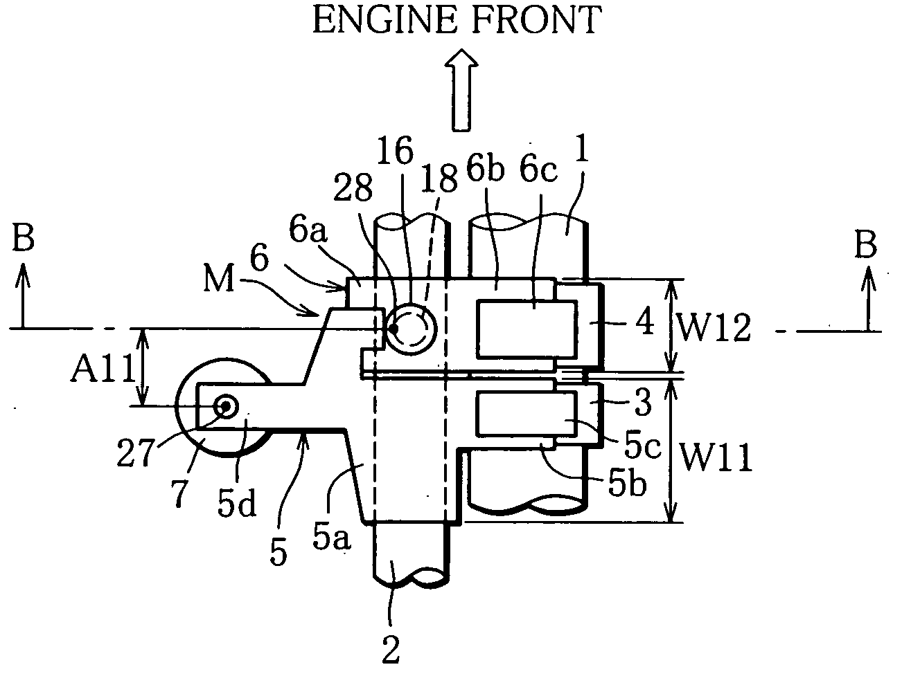
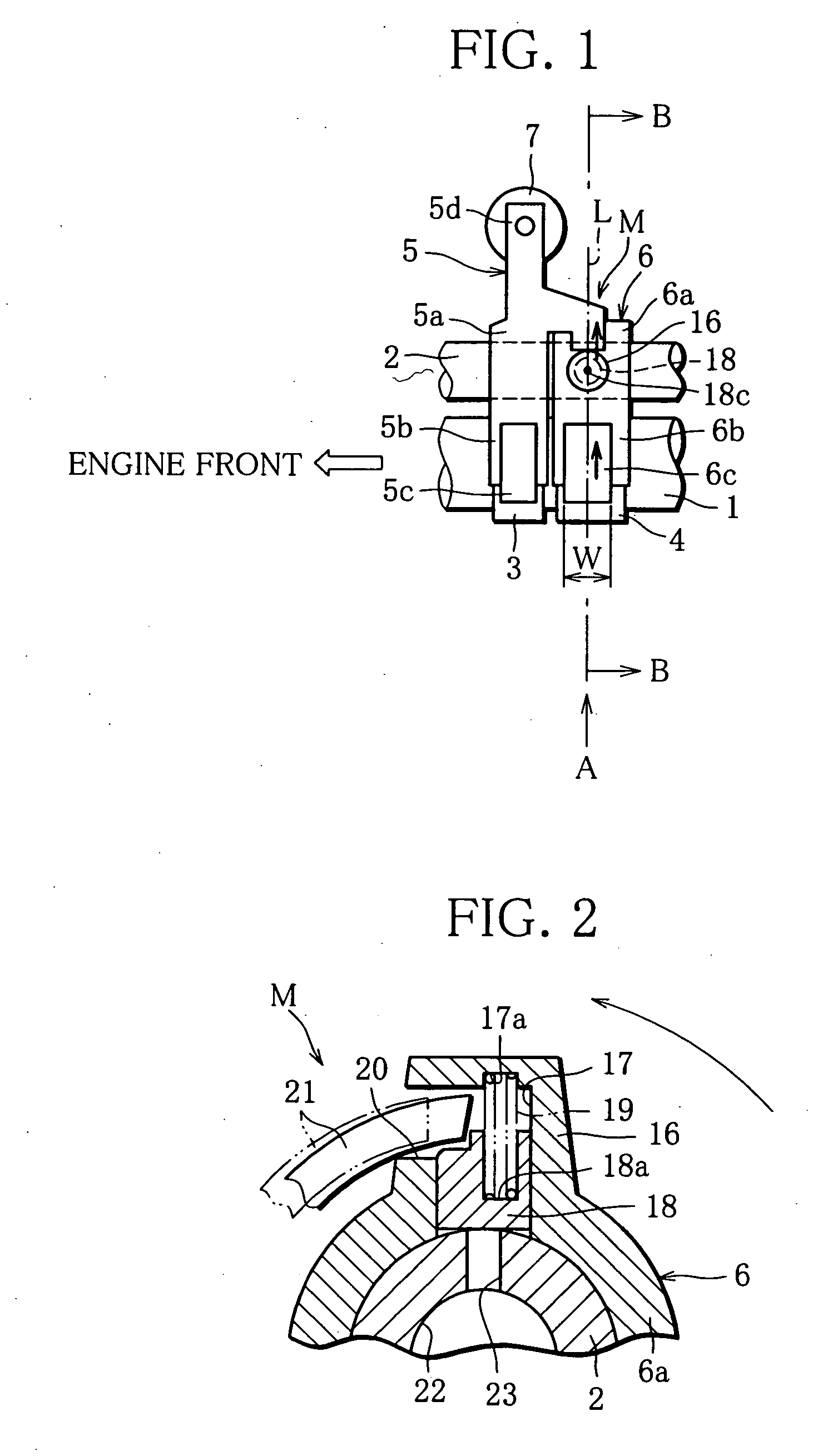
[0067]FIG. 1 is a plan view showing an intake-side part of the variable valve train apparatus according to this embodiment which corresponds to one cylin...

second embodiment

[0083] In the following, a variable valve train apparatus of an engine that embodies this invention will be explained.

[0084] As with the engine according to the first embodiment, the engine of this embodiment is constructed as an in-line four-cylinder SOHC gasoline engine having two valves per cylinder, and is designed to operate in the operation mode which is switchable between a low-speed mode to provide an output characteristic suited to an ordinary rotation zone and a high-speed mode to provide an output characteristic particularly suited to a high-speed rotation zone. To this end, a changeover mechanism for mode switching is provided on the intake side of the variable valve train apparatus for each cylinder. In the following, the construction of the valve driving apparatus for a particular cylinder will be explained, but other cylinders are the same in construction as the particular cylinder. The construction of the changeover mechanism M is the same as that explained in the fi...

third embodiment

[0092] The following is an explanation of a third embodiment in which this invention is embodied in a different variable valve train apparatus for an engine.

[0093] The engine of this invention is constructed in the form of an in-line four-valve SOHC gasoline engine with two valves per cylinder as in the engine of the first embodiment, and is designed to operate in the operation mode which can be changed between a low-speed mode to provide an output characteristic suited to an ordinary rotation zone and a high-speed mode to provide an output characteristic particularly suited to a high-speed rotation zone. To this end, a changeover mechanism for mode switching is provided on the intake side of the variable valve train apparatus for each cylinder. In the following, the construction of the valve driving apparatus for a particular cylinder will be explained, but other cylinders are the same in construction as the particular cylinder. The construction of the changeover mechanism M is the...


PUM


Abstract

A variable valve train apparatus operable in a low-speed mode in which a low-speed rocker arm is rocked by a low-speed cam through a roller or a slipper to thereby open or close an intake valve, and in a high-speed mode in which a high-speed rocker arm is rocked by a high-speed cam through a roller or a slipper and a changeover mechanism part on the side of the low-speed rocker arm is pressed by a changeover mechanism part on the side of the high speed rocker arm together with which the low-speed rocker arm is rocked to open or close the intake valve. The axis of the changeover mechanism part is positioned at the middle of the width of the roller or slipper in the axial direction of the rocker shaft to prevent inclination of the high-speed rocker arm.

Description

CROSS-REFERENCE TO RELATED APPLICATIONS [0001] This nonprovisional application claims priority under 35 U.S.C. §119(a) on Patent Application Nos. 2003-377201, 2003-377202, and 2003-377203 all filed in Japan on Nov. 6, 2003, and Patent Application Nos. 2003-384129, 2003-3484130, and 2003-3484131 all filed in Japan on Nov. 13, 2003, the entire contents of which are hereby incorporated by reference. BACKGROUND OF THE INVENTION [0002] 1. Field of the Invention [0003] This invention relates to a variable valve train apparatus for an internal combustion engine (hereinafter referred to as engine). [0004] 2. Description of the Related Art [0005] To realize optimum engine-output characteristics suitable for individual operating regions, a variety of engines have been proposed that are adapted for example to change a valve-opening period and a lift amount of intake and exhaust valves (refer to Japanese unexamined patent publication nos. 2001-14017, 2-223613, 2003-343225, 7-102921, and 10-1882...

Claims


Application Information

Patent Timeline
Patent Type & Authority Applications(United States)
IPC IPC(8): F01L1/34F01L1/26F01L13/00
CPCF01L2105/00F01L1/267F01L2305/00F01L1/34F01L13/00
Inventor YOKOYAMA, YUUMURATA, SHINICHI
Owner MITSUBISHI MOTORS CORP
Why Eureka
Try Eureka