Gas cooling device

Inactive Publication Date: 2005-05-12
USUI KOKUSAI SANGYO KAISHA LTD
View PDF16 Cites 41 Cited by
  • Summary
  • Abstract
  • Description
  • Claims
  • Application Information

AI Technical Summary

Benefits of technology

[0007] Also, with the EGR gas cooling devices disclosed in JP-A-9-88730 and JP-A-9-88731, there is an advantage that manufacture is easy and cost is low but because of a small heat transfer area, there is a need of specifically increasing an axial length in order to ensure a heat transfer capacity, so that the cooling devices occupy a larg

Problems solved by technology

With the conventional double tube type heat exchangers disclosed in JP-A-11-23181, JP-A-2002-350071, JP-A-2000-111277, and JP-A-2003-21478, however, the pipe that defines an EGR gas flow passage has a smooth, inner peripheral surface over an entire length in a lengthwise direction in many cases, and so there is caused a problem that heat transfer is not adequate in the vicinity of a center of the pipe to lead to a low cooling efficiency of the EGR gas.
Also, with the EGR gas cooling devices disclosed in JP-A-9-88730 and JP-A-9-88731, there is an advantage that

Method used


Image

  • Gas cooling device
  • Gas cooling device
  • Gas cooling device

Examples


Embodiment Construction

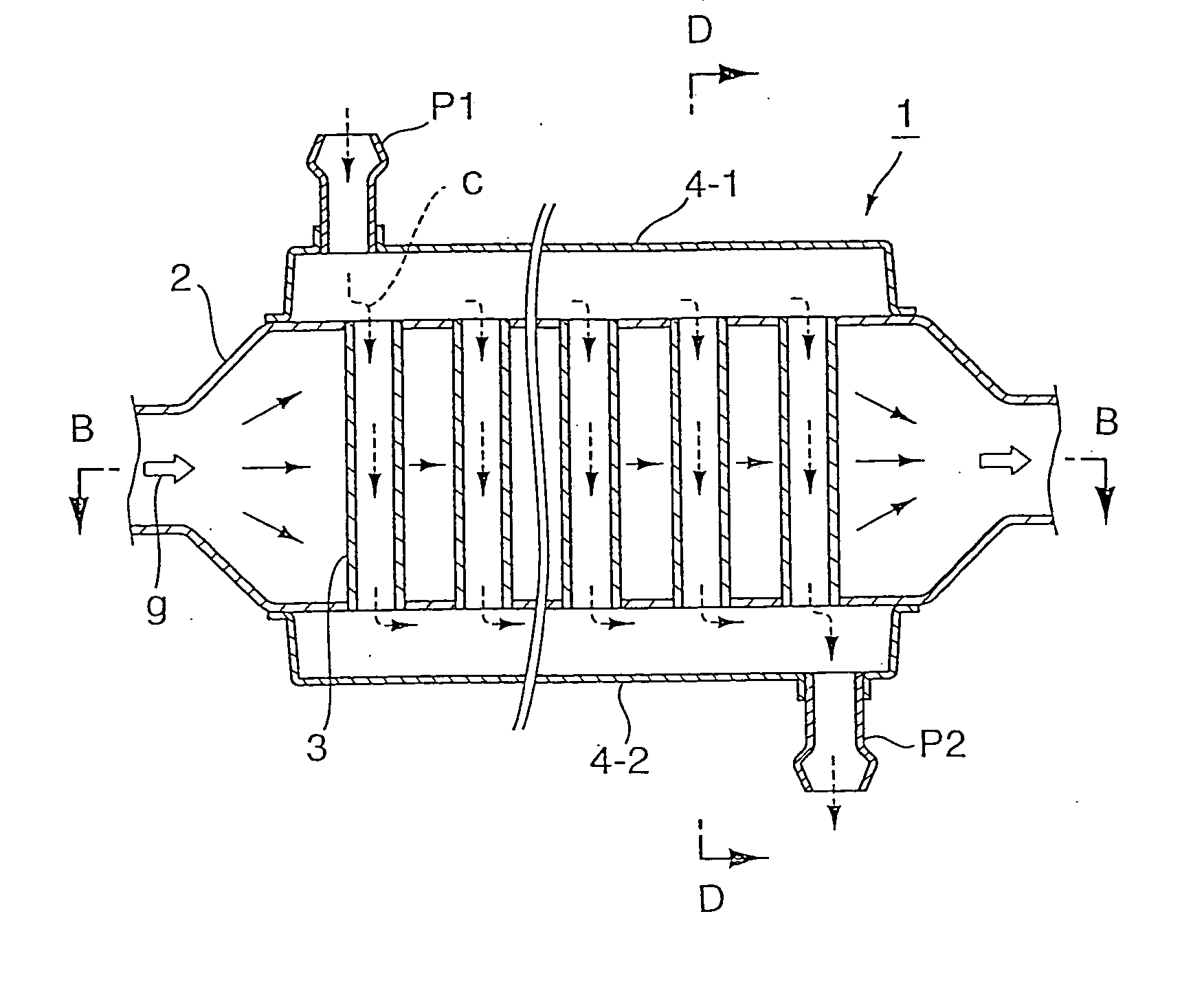
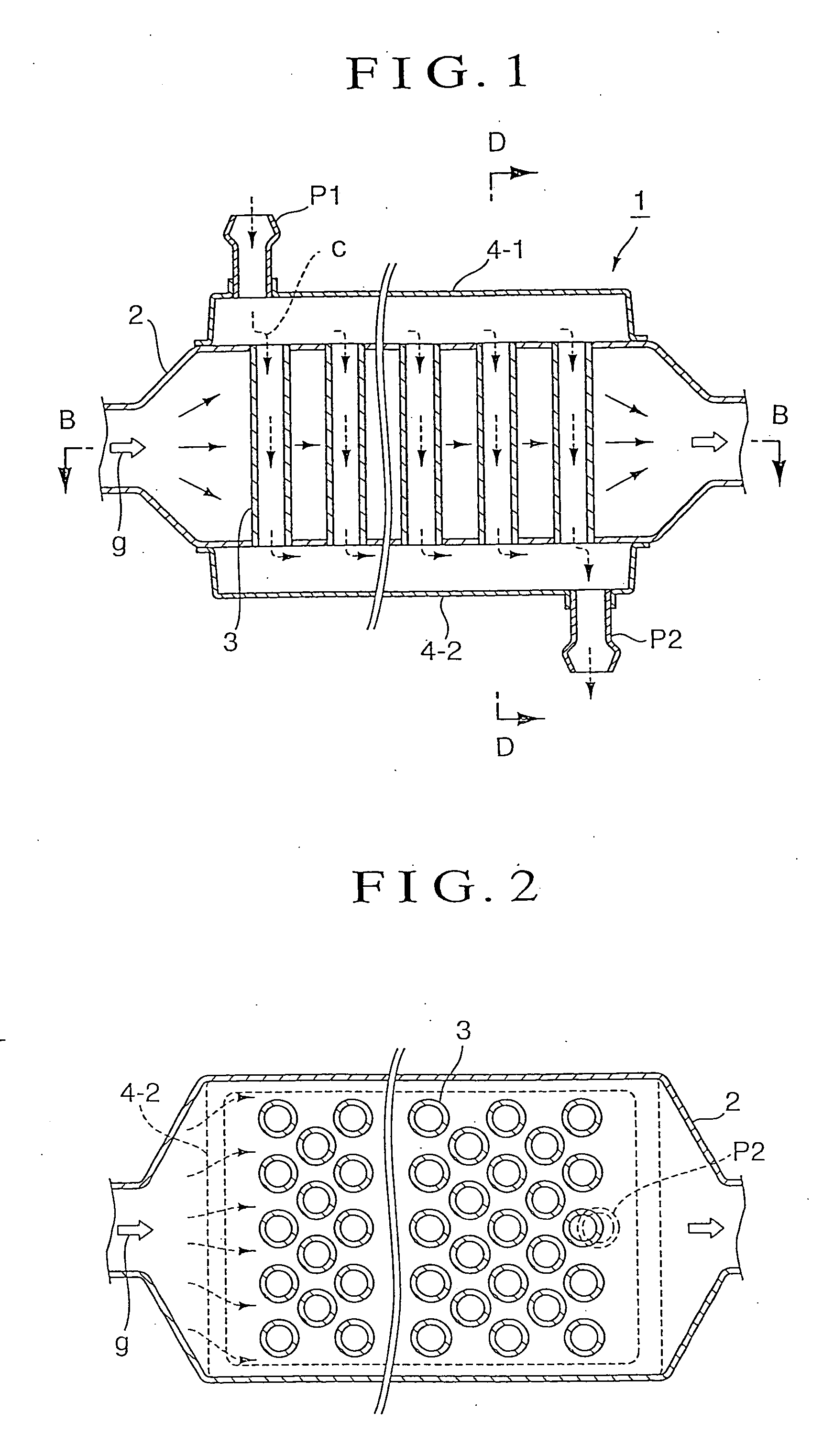
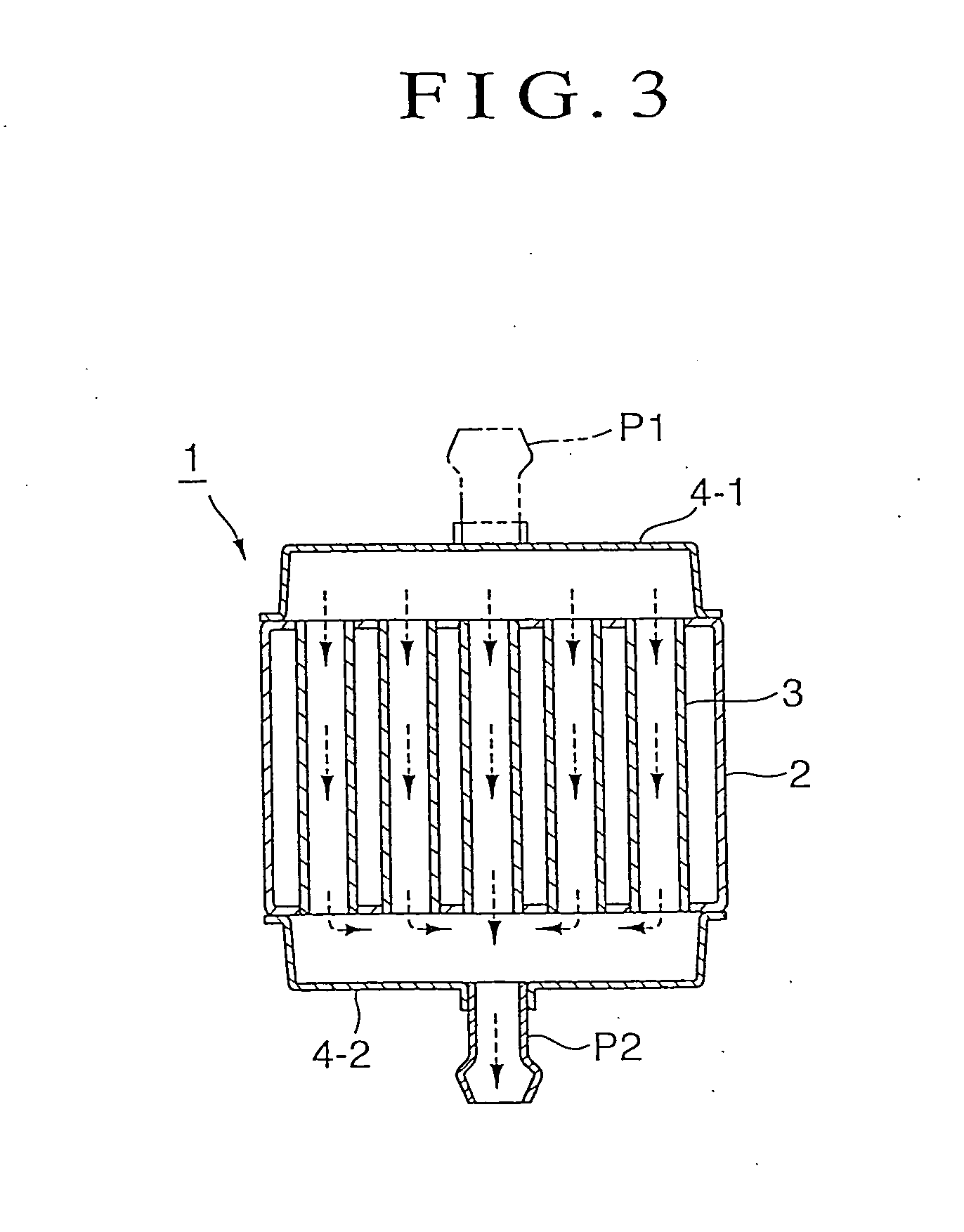
[0031] In the invention, first, an EGR gas cooling device 1 shown in FIGS. 1, 2, and 3 comprises a multiplicity of cooling pipes (heat-transfer pipes) 3 perpendicularly intersecting a gas flow direction (an arrow g) of an EGR gas flowing in an EGR gas pipe 2, which is enlarged in diameter and has a rectangular-shaped cross section, the cooling pipes being fixedly arranged at a predetermined spacing on the EGR gas pipe to extend through an outer peripheral wall of the EGR gas pipe with both pipe ends of the respective cooling pipes opened to an outside. Further, cooling jackets 4-1, 4-2 are fixed to an outer surface of the EGR gas pipe on both sides in an axial direction of the cooling pipes. The cooling jackets 4-1, 4-2, respectively, are provided with an inflow port P1 and an outflow port P2 of a cooling medium.

[0032] With the EGR gas cooling device 1 constructed in the above manner, the EGR gas flowing in a direction of an arrow g within the EGR gas pipe 2 is cooled by the coolin...


PUM


Abstract

A gas cooling device capable of efficiently cooling a gas such as an EGR gas, etc. is provided. A multiplicity of cooling pipes perpendicularly intersecting a gas flow direction in a gas pipe for a gas such as an EGR gas, etc. are provided to extend through an outer peripheral wall of the gas pipe, a cooling jacket is provided on an outer surface of the gas pipe on both sides of a group of the cooling medium pipes in an axial direction, or on the entire outer surface of the gas pipe, and the gas in the gas pipe is cooled by a cooling medium flowing through the cooling pipes.

Description

TECHNICAL FIELD [0001] The present invention relates to a gas cooling device, and more particularly, to a device that cools an EGR gas in an EGR gas pipe at the time of exhaust gas recirculation (referred below to as EGR), in which a part of exhaust gases is taken out from an exhaust system of a diesel engine and returned to an intake system through the EGR gas pipe to be added to a mixture. BACKGROUND ART [0002] A method of taking out a part of exhaust gases from an exhaust system to return the same to an intake system of an engine again to add the same to a mixture is called EGR (Exhaust Gas Recirculation). EGR is thought to be a method that is effective in purification of exhaust gases of an engine and enhancement in thermal efficiency because it produces much effect such as suppression of generation of NOx (nitrogen oxide) reduction in pumping loss, that reduction in radiation loss to a cooling liquid, which is accompanied by temperature drop of combustion gases, an increase in ...

Claims


Application Information

Patent Timeline
IPC IPC(8): F28D7/16F02M25/07
CPCF28D7/1615F28D21/0003F28D7/1653F02M26/32
Inventor GOTO, TADAHIRO
Owner USUI KOKUSAI SANGYO KAISHA LTD
Why Eureka
Try Eureka