Eureka AIR delivers breakthrough ideas for toughest innovation challenges, trusted by R&D personnel around the world.

Recording method for magnetic recording medium, recording device for magnetic recording medium and magnetic recording medium

Active Publication Date: 2005-05-12
SONY CORP
View PDF8 Cites 34 Cited by
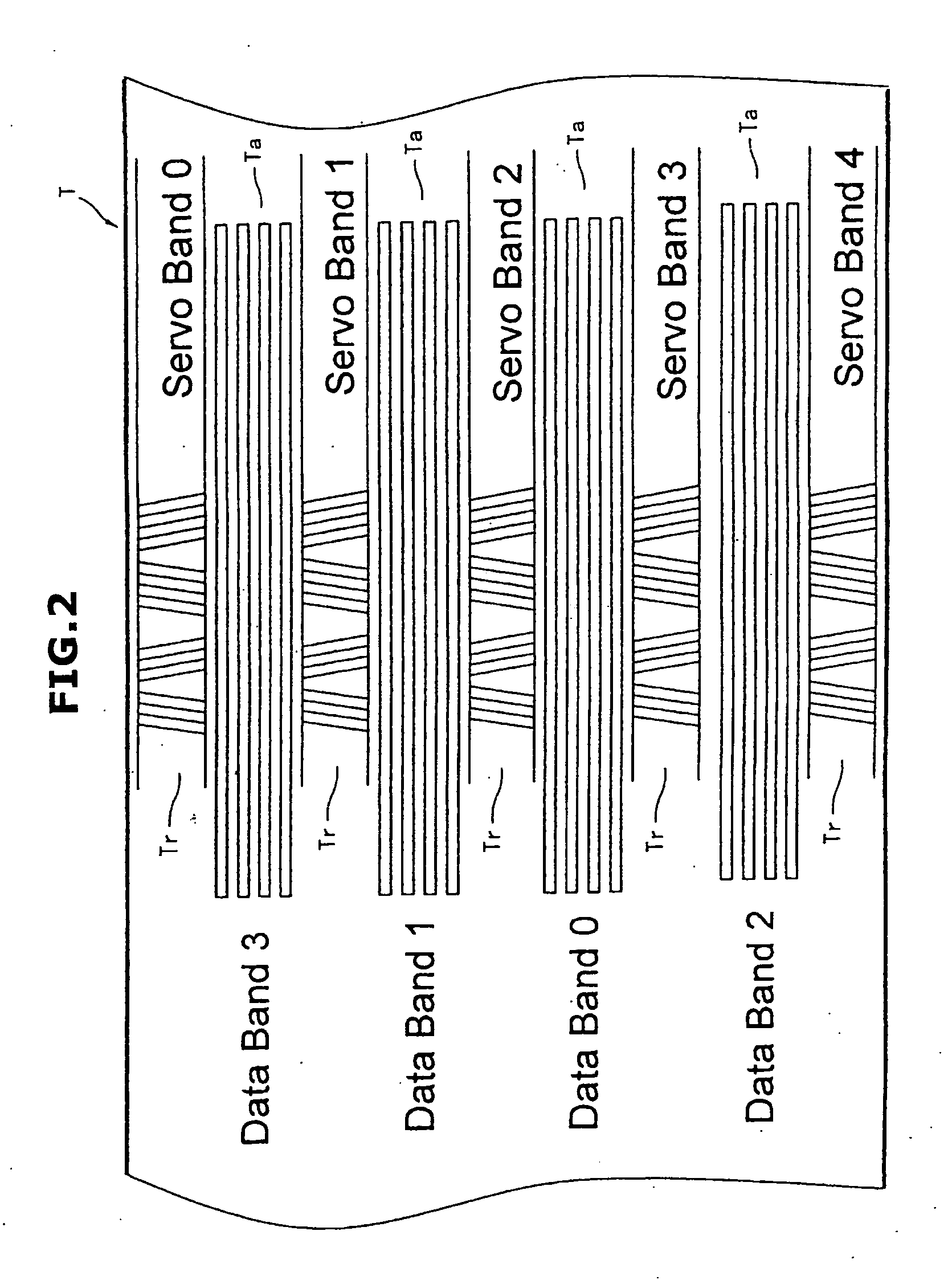
  • Summary
  • Abstract
  • Description
  • Claims
  • Application Information

AI Technical Summary

Benefits of technology

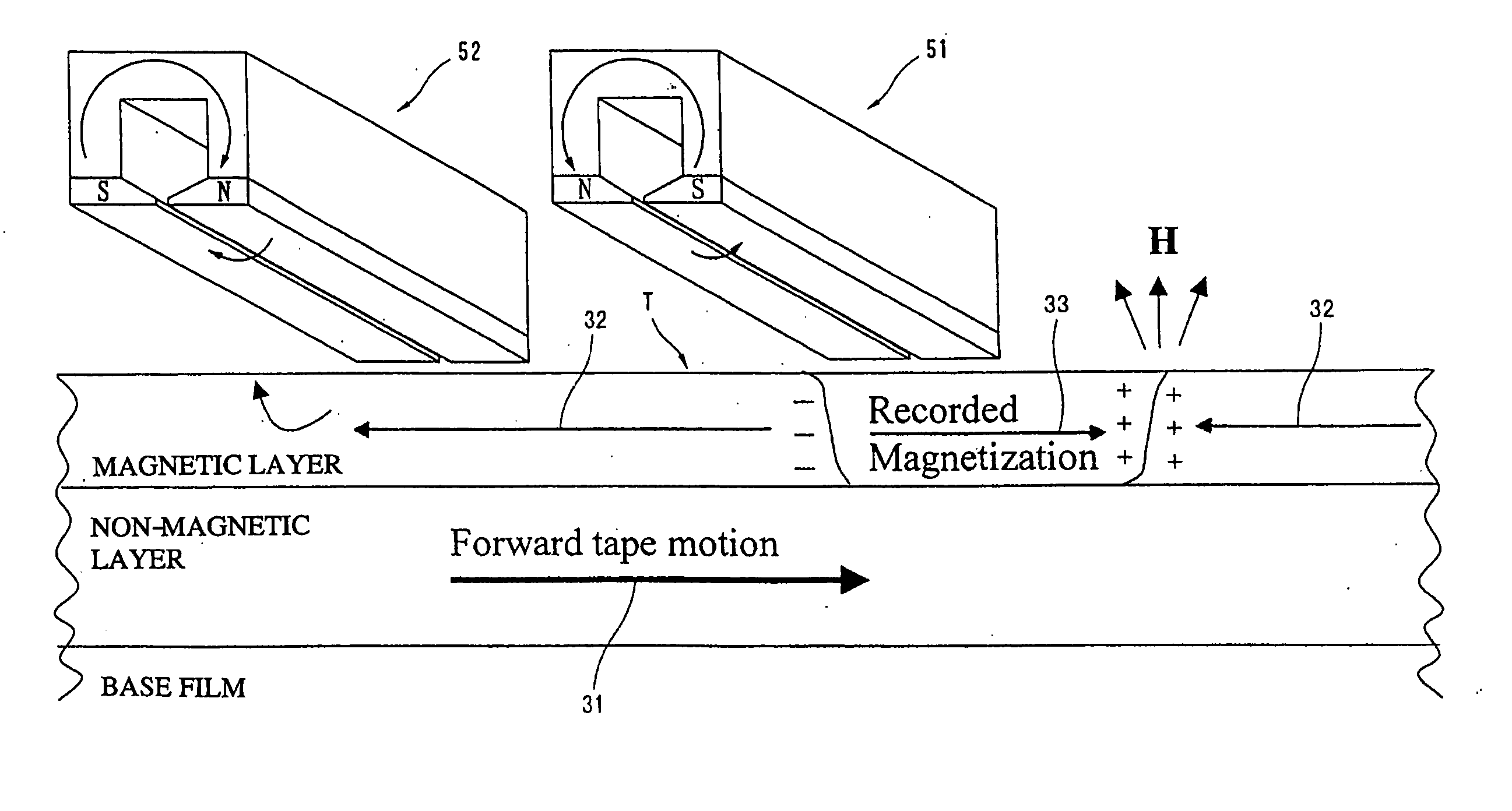
[0028] According to the present invention, the magnetizing direction of the signal recording area by recording the servo signals and the magnetizing direction of a non-signal area by DC erasing the servo signal recording part are opposite to each other. Accordingly, a boundary area in which the magnetizing direction is completely inverted is formed. Thus, a leakage flux is increased more than a conventional method so that a high reproduced output and a high S / N ratio can be obtained upon reproducing the servo signal and the servo signal can be more accurately and rapidly reproduced from the magnetic recording medium on which a high-density recording is carried out.
[0029] Accordingly, a jitter and a defect are reduced and a highly accurate tracking operation can be performed. As a result, a track pitch of the magnetic recording medium can be reduced to increase a recording density.
[0030] The present invention can extremely advantageously obtain the above-described effects in the magnetic recording medium having a magnetic layer of 0.03 μm to 0.13 μm.

Problems solved by technology

Accordingly, when the distances between the recording tracks are too small, interference is generated between the recording tracks.
Thus, the information cannot be precisely recorded and reproduced.
Particularly, when the output of the servo signal is low, the position of the recording and reproducing head cannot be properly controlled.
In an extreme case, a servo head undesirably misses the servo signal.
Further, when time is not precisely recorded (jitter is large), the same problem may be possibly generated.
Therefore, the media in which the thickness of the magnetic layer is smaller than 0.13 μm due to the high density recording can obtain only about half an output by the conventional servo signal recording system, which causes a great trouble for an accurate reproduction of the servo signals.
Further, what is called an evaporated tape in which a metallic thin film is directly formed on a base film also has an important problem to improve a servo output.

Method used


Image

  • Recording method for magnetic recording medium, recording device for magnetic recording medium and magnetic recording medium
  • Recording method for magnetic recording medium, recording device for magnetic recording medium and magnetic recording medium
  • Recording method for magnetic recording medium, recording device for magnetic recording medium and magnetic recording medium

Examples


example 1

[0056] Now, the present invention will be described on the basis of specific experimental results. In a two-layer particulate type media of this example, on a base film made of polyester terephthalate, a non-magnetic layer composed of α-Fe2O3 and polyurethane is formed and a magnetic layer made of Co—Y—Fe ferromagnetic material and polyurethane is formed thereon as shown in FIG. 3.

[0057] (Coating Material for Lower Layer)

α-Fe2O3100parts by weightvinyl chloride copolymer10parts by weight(MR-110 produced by Nippon Zeon Co., Ltd.)polyurethane resin (UR-8300 produced by10parts by weightToyobo Co., Ltd.)carbon black20parts by weightbutyl stearate2parts by weightstearic acid1part by weightmethyl ethyl ketone100parts by weighttoluene50parts by weightcyclohexanone100parts by weight

[0058] The above-described composition was kneaded by an extruder, premixed, then, dispersed by a sand mill, and processed by a filter with a filtration accuracy of 1 μm to prepare a coating material for a lowe...

example 2

[0073] Now, an embodiment in which a DC erasing is performed by using a magnetic head in place of the above-described permanent magnets will be described below by referring to FIGS. 6 and 7. In FIGS. 6 and 7, parts the same as those of FIGS. 1 and 3 are designated by the same reference numerals.

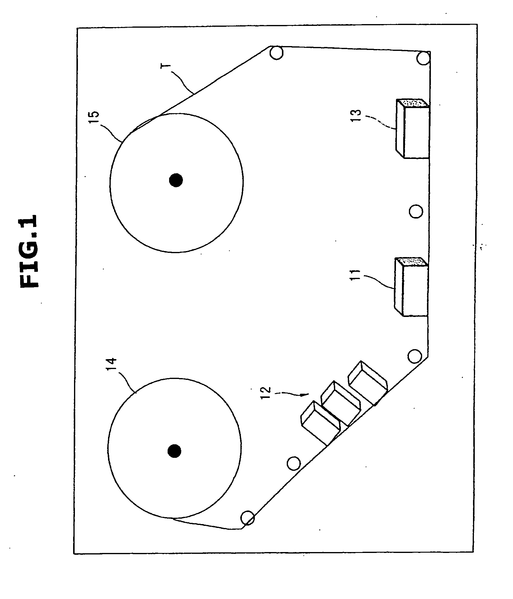
[0074]FIG. 6 shows a servo signal recording device according to this embodiment and is a conceptual view of a device for recording a servo signal S on a magnetic tape T. In FIG. 6, reference numeral 11 designates a recording head unit (servo signal recording means) in which a magnetic head (a recording head) for recording the servo signal S is disposed. Reference numeral 42 designates a servo part demagnetizing unit (DC erasing means) having a demagnetizing head disposed for erasing a servo signal part on the magnetic tape T before a recording operation. 13 designates a reproducing head unit in which a magnetic head (a reproducing head) for reproducing the servo signal S is disposed.

[0075] ...

example 3

[0098] Now, an embodiment in which the present invention is applied to an evaporated tape having a magnetic layer of Co, Ni or the like formed on a base by a vacuum evaporation method will be described below. The present invention is not limited to a below-described Example and may be applied to producing devices and producing methods disclosed, for instance, in Japanese Patent Application Laid-Open Nos. 2003-296919, 2003-85742, 2003-45018, 2003-6851, 2003-346329, 2002-367135 and 2002-245611, and any of metallic thin film type magnetic recording media having a medium structure.

[0099] Now, the present invention will be described on the basis of specific experimental results. In a metallic thin film type magnetic recording medium of this Example, on a base film made of polyester terephthalate, a metallic thin film layer made of Co is formed, and a carbon protective film layer is formed thereon as shown in FIG. 8.

[0100] Initially, a polyethylene terephthalate film having the thicknes...


PUM


Abstract

After a DC erasing is performed in a direction by permanent magnets on a servo signal recording part, servo signals are recorded in the signal recording area of the servo signal recording part by a magnetic field in the direction opposite to that of the DC erasing. Thus, in a recording method for a magnetic recording medium having a data signal recording part and the servo signal recording part on a magnetic layer, accurate servo signals can be recorded and reproduced even on the medium having the magnetic layer of 0.13 μm or smaller.

Description

BACKGROUND OF THE INVENTION [0001] 1. Field of the Invention [0002] The present invention relates to a recording method for a magnetic recording medium, a recording device for a magnetic recording medium and a magnetic recording medium. [0003] 2. Description of the Related Art [0004] In recent years, a demand for a high-density recording has been increased. A property suitable for the high-density recording is also requested for a magnetic recording medium as a recording medium of information. Accordingly, various kinds of improvements are performed on the magnetic recording medium. [0005] For instance, in a linear magnetic tape used for the recording medium of a computer or the like, recording tracks for recording the information in the longitudinal direction of the tape are provided. Distances between the recording tracks are narrowed to improve a track recording density and achieve the high-density recording. [0006] However, when a magnetic head records and reproduces the informa...

Claims


Application Information

Patent Timeline
IPC IPC(8): G11B5/64G11B5/00G11B5/008G11B5/02G11B5/024G11B5/584
CPCG11B5/00G11B5/00813G11B2005/001G11B5/024G11B5/584G11B5/02
Inventor TAKANO, MASANORIABE, TAKASHITAKASU, NOBUFUMIWATANABE, YOSHIYUKIMIYATA, KIYOYUKI
Owner SONY CORP
Why Eureka
Eureka Blog
Learn More