
Yellow phosphor material and white light-emitting device using the same

a technology of white light and yellow phosphor material, which is applied in the direction of semiconductor devices for light sources, sustainable buildings, lighting and heating apparatus, etc., can solve the problems of inability to obtain accurate white light, inability to use plural leds, and inability to obtain blue leds with fixed wavelengths, etc., to achieve convenient use of blue leds, improve color hue, and improve efficiency

Inactive Publication Date: 2005-05-12
LITE ON TECH CORP
View PDF1 Cites 13 Cited by
  • Summary
  • Abstract
  • Description
  • Claims
  • Application Information

AI Technical Summary

Benefits of technology

[0006] It is another object of the present invention to provide a white light-emitting device with phosphor material which has changeable emitting color, thus rendering more flexibility to the blue LED candidate.
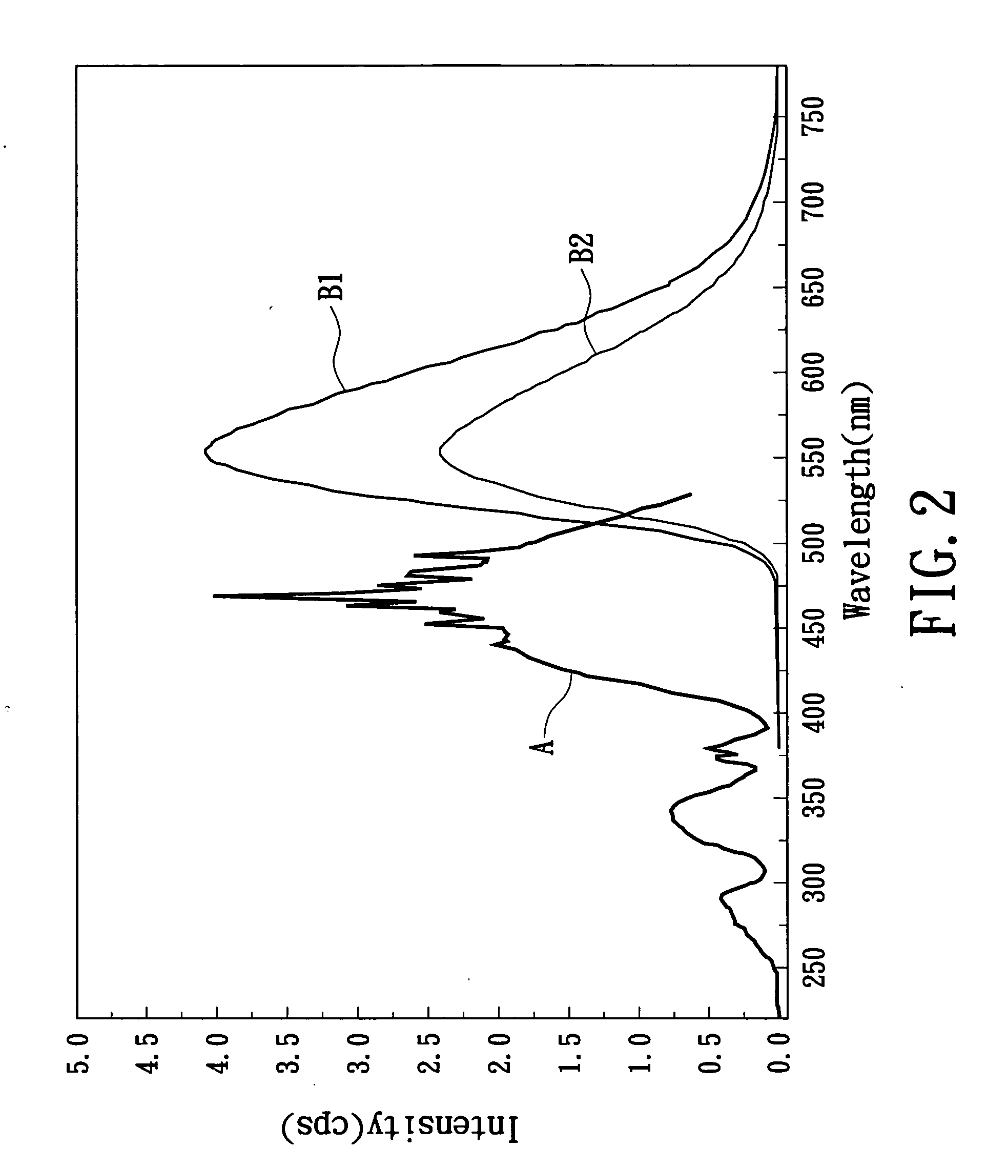
[0008] The above mentioned wavelength-adjustable yellow phosphor material can be used with blue LED of different wavelength to form a white light source with optimal efficiency.
[0009] The white light-emitting device according to the present invention has following particular advantages:
[0010] 1. The long-wavelength (470 nm) blue LED has more difficult manufacture than the short-wavelength (450 nm) blue LED. The wavelength-adjustable property of the phosphor according to the present invention can advantageously facilitate the use of blue LED in short-wavelength regime. Moreover, the short-wavelength (450 nm) blue LED has better color hue to enhance the color rendering property of white light-emitting device using the wavelength-adjustable phosphor.
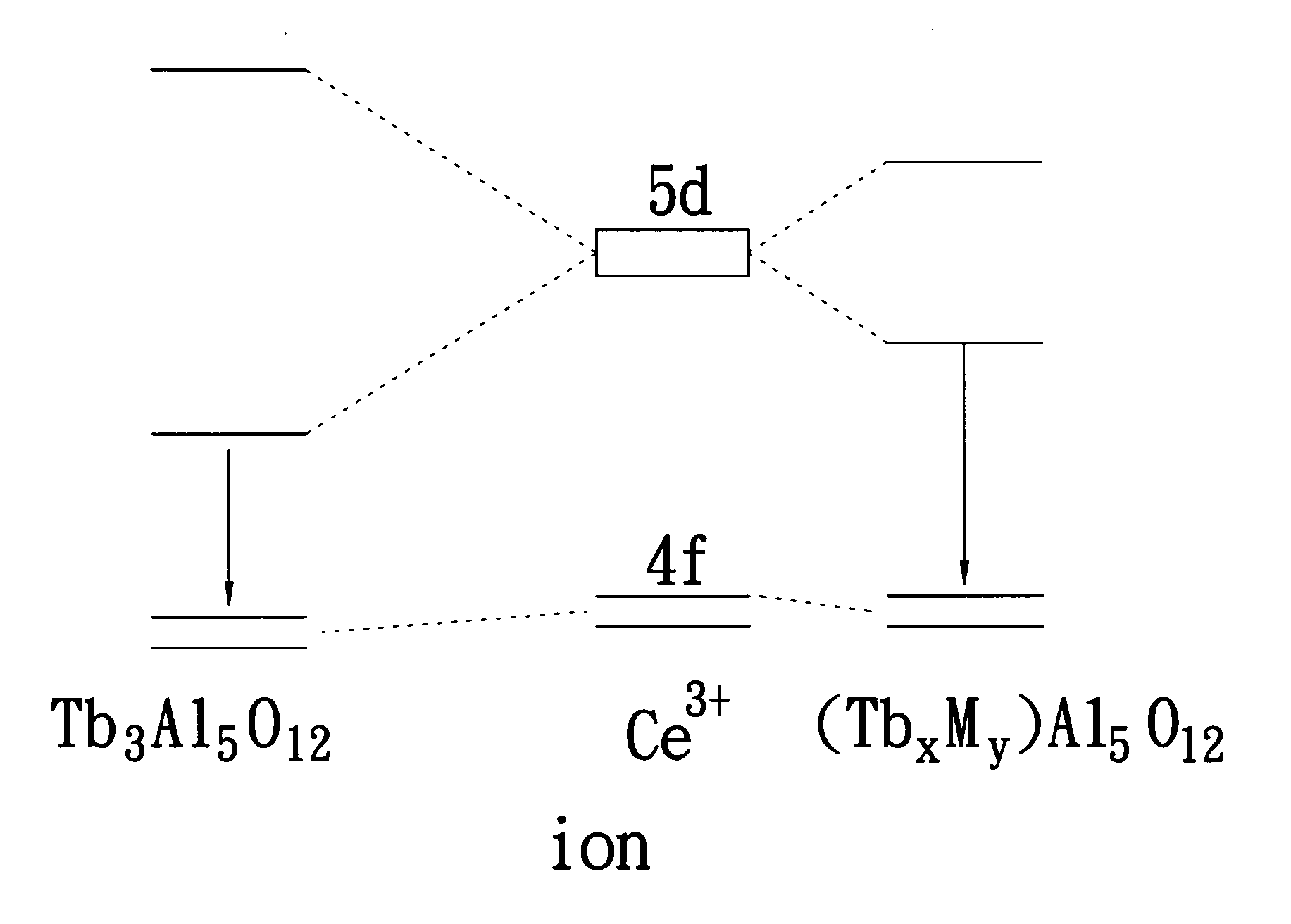
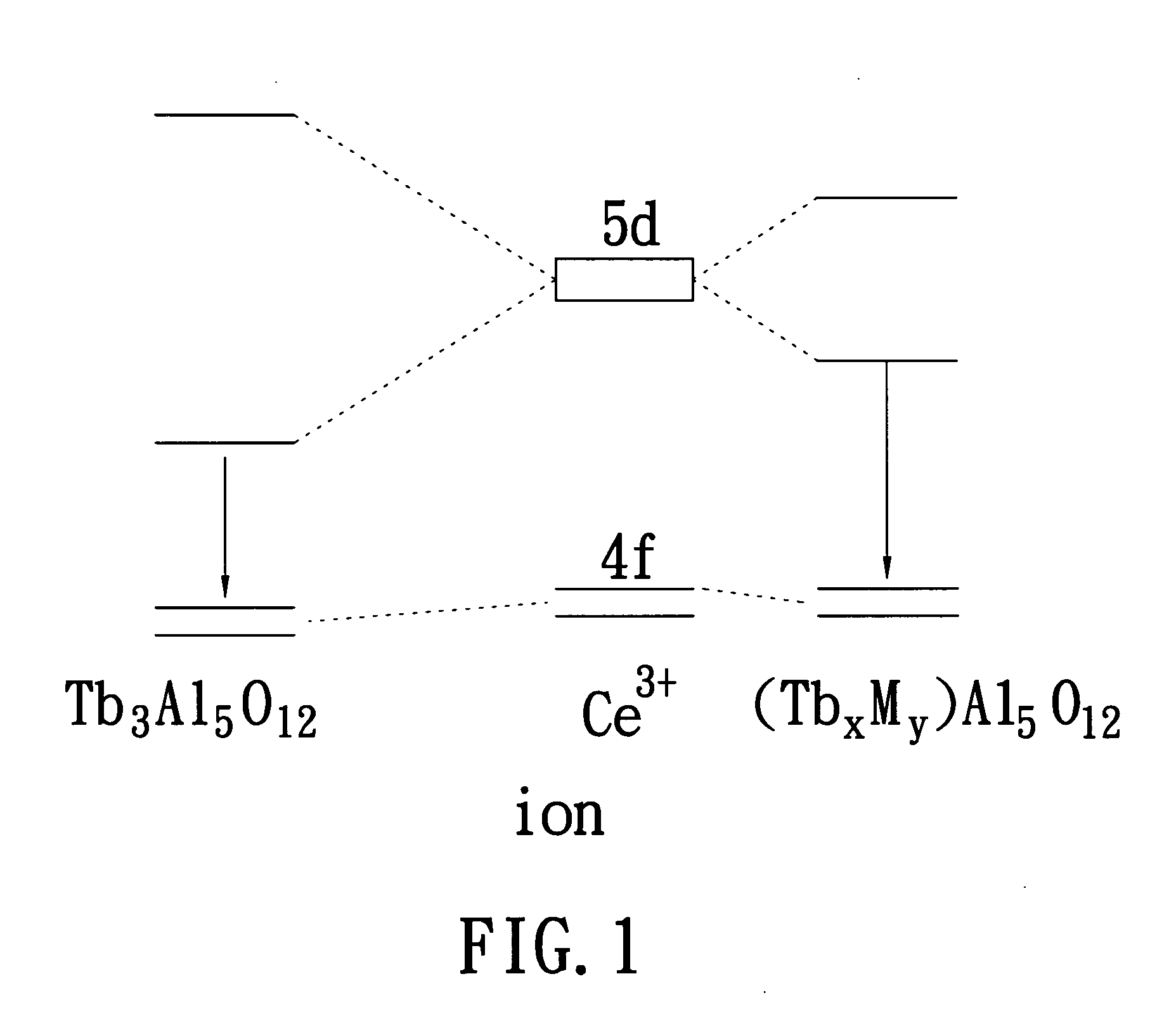
[0011] 2. In the present invention, the luminescent wavelength of phosphor is adjusted by modulating the crystal field of the host matrix of used phosphor instead of changing the amount of hetero ions. The process is simpler and more stable.

Problems solved by technology

These two prior art methods has a common drawback in that when quality of one of the plural LEDs deteriorates, an accurate white light is no longer obtained.
Furthermore, using plural LEDs is costly.
However, so far, since most commercial InGaN type blue LED is made by using metal organic chemical vapor deposition (MOCVD), only blue LED with fixed wavelength can be obtained.
Serious deviation will occur if only slight error in the weight of the hetero ion.

Method used


Image

  • Yellow phosphor material and white light-emitting device using the same
  • Yellow phosphor material and white light-emitting device using the same
  • Yellow phosphor material and white light-emitting device using the same

Examples


example 1

A. EXAMPLE 1

Solid-State Reaction Process

[0024] 1. Preparing mixture for forming a composition having a stoichiometry of (TbxYyCe0.05)Al5O12 (x=0.65 y=2.3 , x=1.15 y=1.8 , x=2.95 y=0) by mixing and grinding Y(NO3)3.6H2O, Al(NO3)3.9H2O, Ce(NO3)3.6H2O, and Tb4O7 matched the stoichiometry.

[0025] 2. Placing thus-produced mixture in a crucible and heating the mixture for calcination in air at 1000° C. with a heating rate of 5° C. / min for 24 hours and followed by cooling down at a cooling rate of 5° C. / min to form intermediate powders.

[0026] 3. Grinding the calcined powder and then placing the calcined powder again in the crucible for sintering in air for 24 hours with temperature ramp and drop of 5° C. / min.

[0027] 4. Placing the sintered powder in a H2 / N2 (5% / 95%) reductive ambient at 1500° C. for 12 hours for reduction. This reduces Ce4+ to Ce3+. It is noted that this step, which can improve light brightness, is optional.

example 2

B. EXAMPLE 2

Citrate Sol-Gel Process

[0028] 1. Preparing a water solution of a composition having a stoichiometry of (TbxYyCe0.05)Al5O12 (x=0.65 y=2.3, x=1.15 y=1.8, x=2.95 y=0) by adding Y(NO3)3.6H2O, Al(NO3)3.9H2O, Ce(NO3)3.6H2O, and Tb4O7 matched the stoichiometry to form a metallic salt and then placing the metallic salt to DI water.

[0029] 2. Adding citrate of the same mole number as the metal ion as chelate agent to the water solution.

[0030] 3. Adding alkali such as ammonia or ethylene diamine to the water solution in step 2 until the pH value thereof exceeding 10.

[0031] 4. Heating the water solution in step 3 by 100˜120° C. until a sticky solution is formed.

[0032] 5. Cooling the sticky solution and the thermal decomposing it in air with 300° C. to remove most organic material and nitride and oxide to obtain a bitumen ash.

[0033] 6. Placing the ash in step 5 in a crucible and heating the mixture for calcination in air at 1000° C. with a heating rate of 5° C. / min for 24 hour...

example 3

C. EXAMPLE 3

Co-Precipitation Process

[0037] 1. Preparing a water solution of a composition having a stoichiometry of (TbxYyCe0.05)Al5O12 (x=0.65 y=2.3, x=1.15 y=1.8, x=2.95 y=0) by adding Y(NO3)3.6H2O, Al(NO3)3.9H2O, Ce(NO3)3.6H2O, and Tb4O7 matched the stoichiometry to form a metallic salt and then placing the metallic salt to DI water.

[0038] 2. Adding alkali such as ammonia or ethylene diamine to the water solution in step 1 until the pH value thereof exceeding 10.

[0039] 3. Stirring the solution in step 2 and obtaining a white sticky solution by pumping and filtering process.

[0040] 4. Thermal decomposing the white sticky solution in step 3 in air with 300° C. to remove most organic material and nitride and oxide to obtain a bitumen ash.

[0041] 5. Placing the ash in step 5 in a crucible and heating the mixture for calcination in air at 1000° C. with a heating rate of 5° C. / min for 24 hours and followed by cooling down at a cooling rate of 5° C. / min to form intermediate powders....


PUM

PropertyMeasurementUnit
domination wavelengthaaaaaaaaaa

Abstract

A yellow phosphor material has a host with a formula (TbxMyCez)Al5O12, wherein x+y+z=3 , 3>x>0 and y≠0 and a Ce activator. M is selected from the group consisting of Sc, Y, Dy, Ho, Er, Tm, Yb, and Lu. By changing the diameter of metal ions, the crystal field thereof may be modulated to thereby alter the energy level of the excited state to which the activator is transferred upon irradiation by a specific wavelength of light. The phosphor can be used with a blue LED to form a white light source.

Description

FIELD OF THE INVENTION [0001] The present invention relates to high-brightness white light-emitting device, especially to a high-brightness white light-emitting device with a purple-blue light or blue light emitting diodes in combination with suitable phosphor to provide white light. BACKGROUND OF THE INVENTION [0002] It is known that the white light is mixed light of different colors. The white light, which is sensed by human eye as white color, at least includes two or more colors of light having different wavelengths. For example, when human eye is stimulated, at the same time, by the Red, Green, and Blue colors of light, or by blue light and yellowish light, a white color is sensed. Accordingly, there have been three major approaches to the formation of white light for now. The first is using R / G / B LEDs. By controlling the current passing the LED to generate white light. The second is using yellow / blue LEDs to generate white light. These two prior art methods has a common drawba...

Claims


Application Information

Patent Timeline
Patent Type & Authority Applications(United States)
IPC IPC(8): C09K11/77F21V9/08H01L33/50
CPCC09K11/7774F21V9/08Y02B20/181H01L33/502F21Y2101/02F21Y2115/10Y02B20/00
Inventor LIU, RU-SHILIN, YI-SHANCHI, LIANG-SHENWANG, CHIEN-YUAN
Owner LITE ON TECH CORP
Learn More