Aerosol method and apparatus, coated particulate products, and electronic devices made therefrom

a technology of coating particulate products and aerosols, which is applied in the direction of chemical/physical/physical-chemical stationary reactors, fixed capacitors, chemical/physical/physical-chemical processes, etc., can solve the problems of unsuitable commercial particle production, uncontrollable liquid precipitation techniques, and contaminated particles prepared by liquid precipitation routes. , to achieve the effect of reducing delamination and other failures, improving compatibility, and improving the compatibility

Inactive Publication Date: 2005-05-12
CABOT CORP
View PDF99 Cites 29 Cited by
  • Summary
  • Abstract
  • Description
  • Claims
  • Application Information

AI Technical Summary

Benefits of technology

[0119] The excess carrier gas 238 that is removed in the aerosol concentrator 236 typically includes extremely small droplets that are also removed from the aerosol 108. Preferably, the droplets removed with the excess carrier gas 238 have a weight average size of smaller than about 1.5 microns, and more preferably smaller than about 1 micron and the droplets retained in the concentrated aerosol 240 have an average droplet size of larger than about 2 microns. For example, a virtual impactor sized to treat an aerosol stream having a weight average droplet size of about three microns might be designed to remove with the excess carrier gas 238 most droplets smaller than about 1.5 microns in size. Other designs are also possible. When using the aerosol generator 106 with the present invention, however, the loss of these very small droplets in the aerosol concentrator 236 will typically constitute no more than about 10 percent by weight, and more preferably no more than about 5 percent by weight, of the droplets originally in the aerosol stream that is fed to the concentrator 236. Although the aerosol concentrator 236 is useful in some situations, it is normally not required with the process of the present invention, because the aerosol generator 106 is capable, in most circumstances, of generating an aerosol stream that is sufficiently dense. So long as the aerosol stream coming out of the aerosol generator 102 is sufficiently dense, it is preferred that the aerosol concentrator not be used. It is a significant advantage of the present invention that the aerosol generator 106 normally generates such a dense aerosol stream that the aerosol concentrator 236 is not needed. Therefore, the complexity of operation of the aerosol concentrator 236 and accompanying liquid losses may typically be avoided.
[0120] It is important that the aerosol stream (whether it has been concentrated or not) that is fed to the furnace 110 have a high droplet flow rate and high droplet loading as would be required for most industrial applications. With the present invention, the aerosol stream fed to the furnace preferably includes a droplet flow of greater than about 0.5 liters per hour, more preferably greater than about 2 liters per hour, still more preferably greater than about 5 liters per hour, even more preferably greater than about 10 liters per hour, particularly greater than about 50 liters per hour and most preferably greater than about 100 liters per hour; and with the droplet loading being typically greater than about 0.04 milliliters of droplets per liter of carrier gas, preferably greater than about 0.083 milliliters of droplets per liter of carrier gas 104, more preferably greater than about 0.167 milliliters of droplets per liter of carrier gas 104, still more preferably greater than about 0.25 milliliters of droplets per liter of carrier gas 104, particularly greater than about 0.33 milliliters of droplets per liter of carrier gas 104 and most preferably greater than about 0.83 milliliters of droplets per liter of carrier gas 104.
[0121] One embodiment of a virtual impactor that could be used as the aerosol concentrator 236 will now be described with reference to FIGS. 26-32. A virtual impactor 246 includes an upstream plate assembly 248 (details shown in FIGS. 27-29) and a downstream plate assembly 250 (details shown in FIGS. 30-32), with a concentrating chamber 262 located between the upstream plate assembly 248 and the downstream plate assembly 250.
[0122] Through the upstream plate assembly 248 are a plurality of vertically extending inlet slits 254. The downstream plate assembly 250 includes a plurality of vertically extending exit slits 256 that are in alignment with the inlet slits 254. The exit slits 256 are, however, slightly wider than the inlet slits 254. The downstream plate assembly 250 also includes flow channels 258 that extend substantially across the width of the entire downstream plate assembly 250, with each flow channel 258 being adjacent to an excess gas withdrawal port 260.
[0123] During operation, the aerosol 108 passes through the inlet slits 254 and into the concentrating chamber 262. Excess carrier gas 238 is withdrawn from the concentrating chamber 262 via the excess gas withdrawal ports 260. The withdrawn excess carrier gas 238 then exits via a gas duct port 264. That portion of the aerosol 108 that is not withdrawn through the excess gas withdrawal ports 260 passes through the exit slits 256 and the flow channels 258 to form the concentrated aerosol 240. Those droplets passing across the concentrating chamber 262 and through the exit slits 256 are those droplets of a large enough size to have sufficient momentum to resist being withdrawn with the excess carrier gas 238.
[0124] As seen best in FIGS. 27-32, the inlet slits 254 of the upstream plate assembly 248 include inlet nozzle extension portions 266 that extend outward from the plate surface 268 of the upstream plate assembly 248. The exit slits 256 of the downstream plate assembly 250 include exit nozzle extension portions 270 extending outward from a plate surface 272 of the downstream plate assembly 250. These nozzle extension portions 266 and 270 are important for operation of the virtual impactor 246, because having these nozzle extension portions 266 and 270 permits a very close spacing to be attained between the inlet slits 254 and the exit slits 256 across the concentrating chamber 262, while also providing a relatively large space in the concentrating chamber 262 to facilitate efficient removal of the excess carrier gas 238.

Problems solved by technology

Such liquid precipitation techniques are often difficult to control to produce particles with the desired characteristics.
Also, particles prepared by liquid precipitation routes often are contaminated with significant quantities of surfactants or other organic materials used during the liquid phase processing.
Spray pyrolysis systems have, however, been mostly experimental, and unsuitable for commercial particle production.
Also, spray pyrolysis systems are often inefficient in the use of carrier gases that suspend and carry liquid droplets of the aerosol.
For example, there is a significant problem in cofire processes, such as cofiring of multi-layer ceramic capacitors and other components, of delaminations and other failures that can occur due to sintering / densification / shrinkage mismatch between adjoining layers.

Method used


Image

  • Aerosol method and apparatus, coated particulate products, and electronic devices made therefrom
  • Aerosol method and apparatus, coated particulate products, and electronic devices made therefrom
  • Aerosol method and apparatus, coated particulate products, and electronic devices made therefrom

Examples


example 1

[0268] This example demonstrates preparation of multi-phase particles of either neodymium titanate or barium titanate with various metals.

[0269] A titanate precursor solution is prepared for each of barium titanate and neodymium titanate. The barium titanate precursor solution is prepared by dissolving barium nitrate in water and then, with rapid stirring, adding titanium tetraisopropoxide. A fine precipitate is formed. Sufficient nitric acid is added to completely dissolve the precipitate. Precursor solutions of various metals are prepared by dissolving the metal salt in water. The neodymium titanate precursor solution is prepared in the same way except using neodymium nitrate.

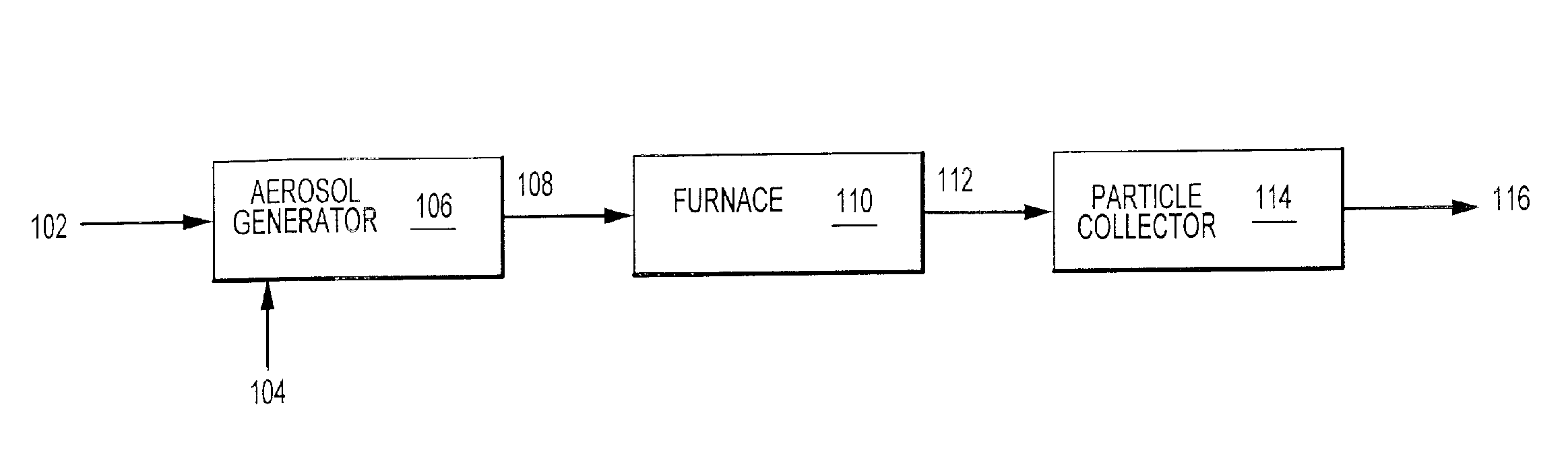
[0270] The titanate precursor solution and the metal precursor solution are mixed in various relative quantities to obtain the desired relative quantities of titanate and metal components in the final particles. The mixed solutions are aerosolized in an ultrasonic aerosol generator with transducers operated...

example 2

[0272] A variety of materials are made according to the process of the present invention, with some materials being made with and some being made without droplet classification prior to the furnace. Various single phase and multi-phase (or composite) particles are made as well as several coated particles. Tables 3 through 8 tabulate various of these materials and conditions of manufacture.

TABLE 2CompositeMetal Precursor(s)Temperature ° C.Carrier Gas75 / 25 Pd / BaTiO3nitrate1000N2Ag:Pd / BaTiO3(1)nitrate600-1100air75 / 25nitrate1000airAg:Pd / BaTiO375 / 25 Ni / BaTiO3nitrate1200N2 + H275 / 25nitrate1200N2 + H2Ni / Ne2TiO775 / 25 Cu / BaTiO3nitrate1200N2 + H275 / 25 Cu / BaTiO7nitrate1200N2 + H250 / 50 Pt / BaTiO3chloroplatinic acid1100air

(1)70:30 Ag:Pd alloy, BaTiO3 varied from 5 to 90 weight percent of the composite.

(2)30:70 Ag:Pd alloy.

[0273]

TABLE 3PhosphorsCar-ReactorrierMaterialPrecursor(4)Temp ° C.GasY2O3:EuYttrium nitrate, chloride or ace-500-1100Airdopanttate and europium nitrate(1)(2)CaTiO3Titanium t...


PUM

PropertyMeasurementUnit
weight average particle sizeaaaaaaaaaa
weight percentaaaaaaaaaa
thicknessaaaaaaaaaa

Abstract

Provided is an aerosol method, and accompanying apparatus, for preparing powdered products of a variety of materials involving the use of an ultrasonic aerosol generator (106) including a plurality of ultrasonic transducers (120) underlying and ultrasonically energizing a reservoir of liquid feed(102) which forms droplets of the aerosol. Carrier gas (104) is delivered to different portions of the reservoir by a plurality of gas delivery ports (136) delivering gas from a gas delivery system. The aerosol is pyrolyzed to form particles, which are then cooled and collected. The invention also provides powders that include coated particles made by the method and devices made using the coated particles.

Description

CROSS-REFERENCE TO RELATED APPLICATIONS [0001] This application is a continuation application of U.S. patent application Ser. No. 10 / 653,722 filed Sep. 2, 2003, which is a continuation application of U.S. patent application Ser. No. 09 / 668,947 filed Sep. 22, 2000, now U.S. Pat. No. 6,635,348, which is a divisional application of U.S. patent application Ser. No. 09 / 030,057 filed Feb. 24, 1998, now U.S. Pat. No. 6,338,809, which claims priority to U.S. Provisional Patent Application No. 60 / 039,450 filed Feb. 24, 1997 and to U.S. Provisional Patent Application No. 60 / 038,258 filed Feb. 24, 1997. The foregoing patent applications are incorporated herein by reference in their entirety.FIELD OF THE INVENTION [0002] The present invention involves aerosol production of finely-divided particles of a variety of compositions. The present invention also involves the particles so manufactured and electronic devices made using the particles. BACKGROUND OF THE INVENTION [0003] Powdered materials a...

Claims


Application Information

Patent Timeline
Patent Type & Authority Applications(United States)
IPC IPC(8): B01J2/00B01J2/02B01J2/04B01J2/16B01J2/18B01J13/02B01J19/00B01J19/10B01J19/24B22F1/054B22F1/16B22F1/17B22F9/02B22F9/24B24B37/04C01B13/18C01B17/20C01G15/00C01G23/00C01G25/00C09G1/02C09K3/14C09K11/02C09K11/08C09K11/56C09K11/58C09K11/59C09K11/62C09K11/64C09K11/66C09K11/67C09K11/77C22C1/10C22C32/00H01G4/008H01J29/20H01L21/321H01L23/498
CPCB01J2/003B01J2/006B01J2/02B01J2/04B01J13/02B01J19/10B01J19/2405B01J2219/00112B01J2219/00155B01J2219/00159B01J2219/00162B01J2219/00166B01J2219/00171B01J2219/00186B22F1/0018B22F1/02B22F1/025B22F9/02B22F9/026B22F9/24B22F9/30B22F2998/00B22F2999/00B24B37/044B82Y30/00C01B13/18C01B13/185C01B17/20C01G15/006C01G23/003C01G23/006C01G25/00C01P2002/60C01P2002/70C01P2004/03C01P2004/32C01P2004/34C01P2004/50C01P2004/52C01P2004/61C01P2004/62C01P2004/80C01P2006/10C01P2006/22C01P2006/60C01P2006/80C09G1/02C09K3/1436C09K3/1463C09K11/025C09K11/0805C09K11/0877C09K11/562C09K11/565C09K11/567C09K11/584C09K11/595C09K11/623C09K11/625C09K11/642C09K11/643C09K11/644C09K11/662C09K11/666C09K11/671C09K11/672C09K11/7701C09K11/7708C09K11/7718C09K11/7729C09K11/7731C09K11/7734C09K11/7746C09K11/7769C09K11/7771C09K11/7774C09K11/7776C09K11/7784C09K11/7786C09K11/7787C09K11/7789C09K11/7797C22C1/1026C22C32/0089H01G4/0085H01J29/20H01L21/3212H01L23/49883H01L2924/09701H01L2924/0002Y10T428/12056Y10T428/2991Y10T428/1216Y10T428/2982Y10T428/12014Y10T428/12181Y10T428/256Y10T428/12007B22F1/0014B22F1/0048B22F2202/01B22F3/008B22F2202/11H01L2924/00Y02P10/25B22F1/17B22F1/16B22F1/054B22F10/10B22F1/052B22F1/065
Inventor HAMPDEN-SMITH, MARK J.KODAS, TOIVO T.POWELL, QUINT H.SKAMSER, DANIEL J.CARUSO, JAMESCHANDLER, CLIVE D.
Owner CABOT CORP
Why Eureka
Try Eureka