
Fluorescence detection instrument with reflective transfer legs for color decimation

a technology of color decimation and fluorescence detection, which is applied in the direction of fluorescence/phosphorescence, luminescent dosimeters, optical radiation measurement, etc., can solve the problem that other angles will not work as efficiently

Inactive Publication Date: 2005-05-19
BECTON DICKINSON & CO
View PDF12 Cites 18 Cited by
  • Summary
  • Abstract
  • Description
  • Claims
  • Application Information

AI Technical Summary

Benefits of technology

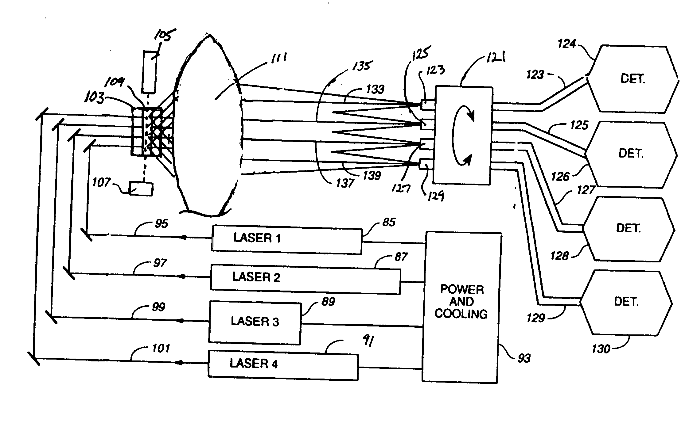
[0010] By maintaining spatial separation for the input beams, spatial separation can be preserved in the output transfer beams, with each transfer beam directed into an optical fiber for delivery to a detector cluster. This allows detector clusters to be stacked or placed in racks, with optical fibers carrying transfer beams to the location of an input port of each cluster. Once inside of a cluster, the transfer beam is decimated by the dichroic beam splitters, each beam splitter inclined to a transfer leg at a preferred angle centered on 11.25 degrees. Other angles will work but not as efficiently. Each beam splitter achieves color separation in the usual way, i.e. by transmitting light of a particular wavelength. This transmitted light is directed to a photomultiplier tube, or the like, which is positioned, to the extent possible, to detect light in the transmitted detector legs associated with the split beam. A focusing lens and the detector photomultiplier tubes are positionally relatively adjustable so that an optimum detector position can be found by motion of a detector element relative to a lens focusing incoming light. In this manner, the fluorescence associated with each of several laser beams is simultaneously decimated into bands characteristic of the target material within the detector array of each cluster. A group of clusters provides color decimation much greater than heretofore available. Moreover, the apparatus is modular because a greater number of fibers can feed a greater number of clusters. One of the advantages of using a reflective transfer leg to relay the optical signal for decimation, rather than the transmitted leg, is that the reflective transfer leg is a stronger optical signal. After encounters with several beam splitters, the signal attenuation in a relayed reflective transfer leg signal is substantially greater than for an optical signal in which the relay was transmitted through an equal number of beam splitters, as in the prior art.

Problems solved by technology

Other angles will work but not as efficiently.

Method used


Image

  • Fluorescence detection instrument with reflective transfer legs for color decimation
  • Fluorescence detection instrument with reflective transfer legs for color decimation
  • Fluorescence detection instrument with reflective transfer legs for color decimation

Examples


Embodiment Construction

[0027] With reference to FIG. 4, a first laser 85, a second laser 87, a third laser 89, and a fourth laser 91, all produce light with unique wavelength profiles and all are connected to respective power supplies and a cooling module 93. The lasers emit respective beams 95, 97, 99 and 101 which are directed by means of beam-turning mirrors toward flow stream 103 causing the beams to intersect with the stream. Although the preferred embodiment features a flow cytometer, this instrument is merely illustrative of instruments which employ fluorescence detection and color separation. Other instruments include microscopes, electrophoresis instruments, spectrophotometers, and the like. The scope of the present invention is therefore not limited to flow cytometers.

[0028] A fluidic system 105 feeds tagged target liquid substances into a stream 103 in a controlled manner. Material which passes through the beam illuminated zone is collected in collection cup 107. The illuminated zone is establ...


PUM


Abstract

An optical instrument using a plurality of lasers of different colors with parallel, closely spaced beams to stimulate scattering and fluorescence from fluorescent biological particulate matter, including cells and large molecules. A large numerical aperture objective lens collects fluorescent light while maintaining spatial separation of light stimulated by the different sources. The collected light is imaged into a plurality of fibers, one fiber associated with each optical source, which conducts light to a plurality of arrays of detectors, with each array associated with light from one of the fibers and one of the lasers. A detector array has up to ten detectors arranged to separate and measure colors within relatively narrow bands by decimation of light arriving in a fiber. A large number of detectors is mounted in a compact polygonal arrangement by using reflective transfer legs from multiple beam splitters where the transfer legs arise from a polygonal arrangement of beam splitters in a circumference within the circumferential arrangement of detectors.

Description

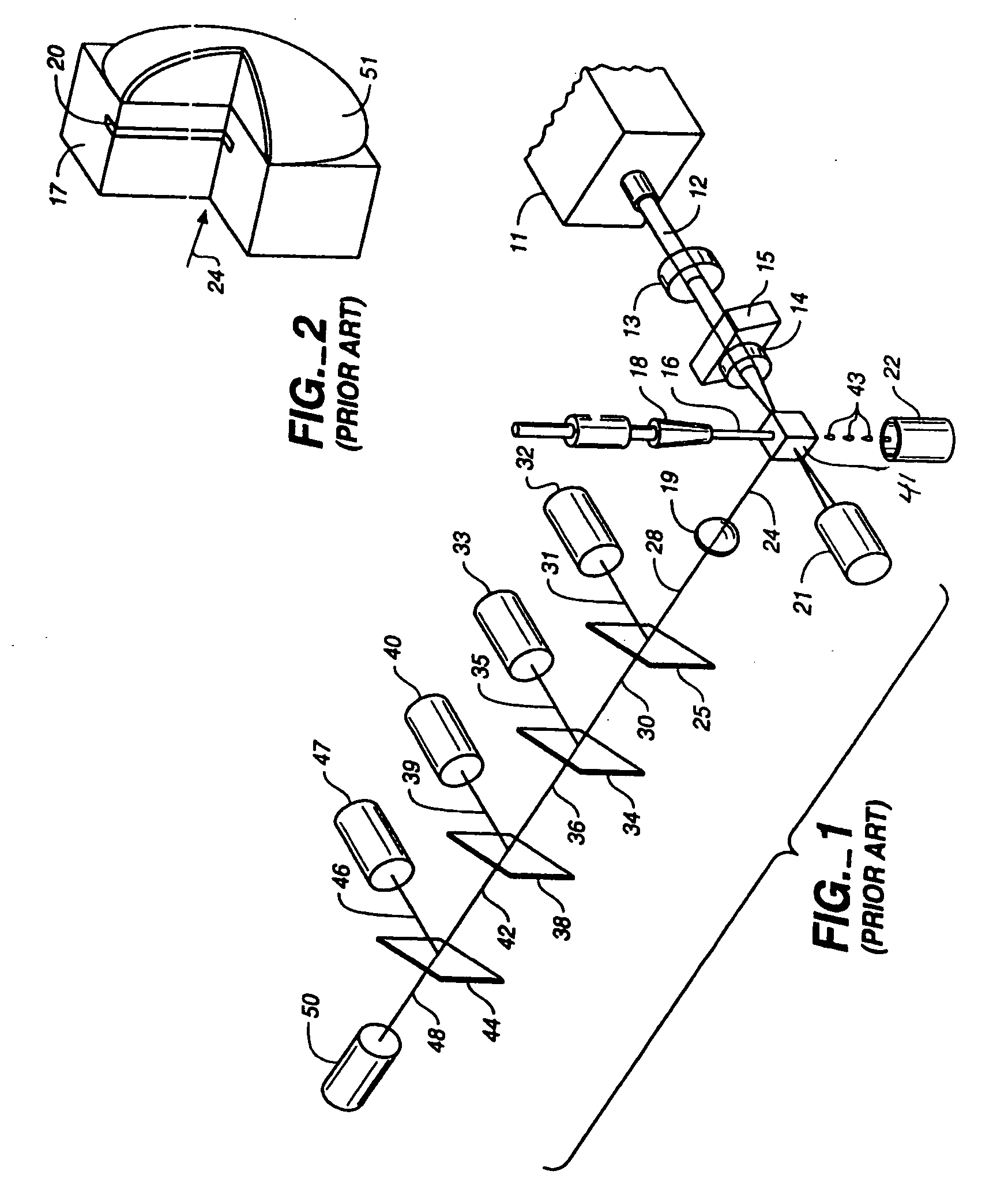
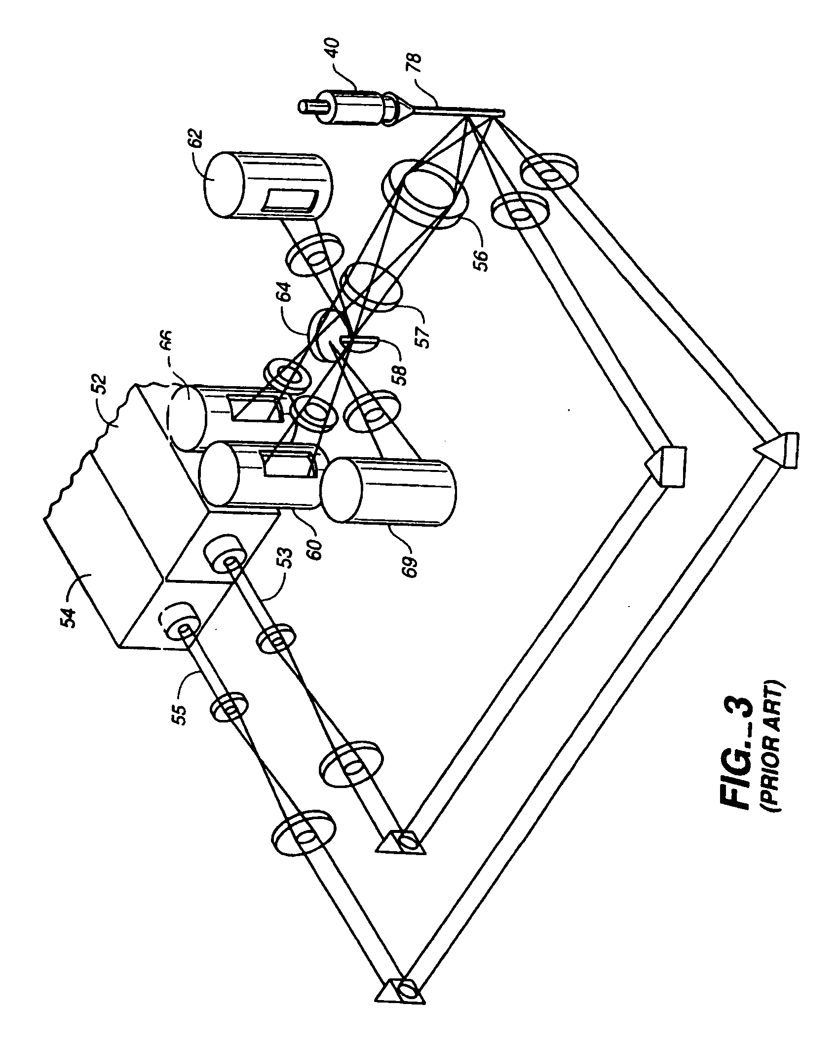
TECHNICAL FIELD [0001] The invention relates to analytical instruments for flourescent light analysis from target specimens and, more particularly, to such an instrument employing increased color decomposition of fluorescent signals from target substances. BACKGROUND ART [0002] As an example of fluorescent light decomposition for bioanalytical studies, in high throughput screening, the ability to simultaneously detect a plurality of fluorescent dyes with good wavelength discrimination enables deeper multiplexing and higher throughput. In another example using fluorescent light analysis, simultaneous detection of multiple dyes associated with cells allows simultaneous assay of cell surface antigens, organelle states, nucleic acid assay, and intercellular protein content to be detected in a single assay. Multiple wavelength detection requires detectors which can separate many bands of colors. This has commonly been done using dichroic mirror beam splitters. [0003] U.S. Pat. No. 5,317,...

Claims


Application Information

Patent Timeline
IPC IPC(8): G01N21/64
CPCG01J3/02G01N2021/6484G01J3/0205G01J3/0208G01J3/021G01J3/0237G01J3/0291G01J3/10G01J3/36G01J3/4406G01N21/6428G01N21/645G01N2021/6419G01N2021/6421G01N2021/6463G01J3/0202
Inventor OOSTMAN, CLIFFORD A. JR.BLASENHEIM, BARRY J.
Owner BECTON DICKINSON & CO
Learn More