Focused beam spectroscopic ellipsometry method and system

a spectroscopic ellipsometry and focused beam technology, applied in the direction of optical radiation measurement, instruments, polarisation-affecting properties, etc., can solve the problems of undetectable effects, undetectable effects, and unsuitable use of transmissive optics, so as to eliminate chromatic aberration in the focused beam, avoid aberration and other undesirable effects, and reduce off-axis aberration

Inactive Publication Date: 2005-05-19
PIWONKA CORLE TIMOTHY R +6
View PDF52 Cites 9 Cited by
  • Summary
  • Abstract
  • Description
  • Claims
  • Application Information

AI Technical Summary

Benefits of technology

[0011] The spectroscopic ellipsometry method and apparatus of the invention employs reflective optics to measure a small (and preferably compact) region of a sample (e.g., a microscopically small, square-shaped spot on the sample) by reflecting broadband radiation having a range of UV (and preferably also visible and near infrared) wavelengths from the region. The method and apparatus of the invention optionally also determines from the measurements the thickness and/or complex refractive index of a thin film on the sample (such as a layer of a multiple layer stack over a silicon substrate of a semiconductor wafer). Preferred embodiments of the inventive ellipsometer employ only reflective optics (along the optical path betwee...

Problems solved by technology

However, it had not been known how to accomplish this using an ellipsometer with all-reflective optics (for use with broadband UV radiation).
The inventors have recognized that such transmissive optics are unsuitable for use with broadband radiation of ultraviolet...

Method used


Image

  • Focused beam spectroscopic ellipsometry method and system
  • Focused beam spectroscopic ellipsometry method and system
  • Focused beam spectroscopic ellipsometry method and system

Examples


Embodiment Construction

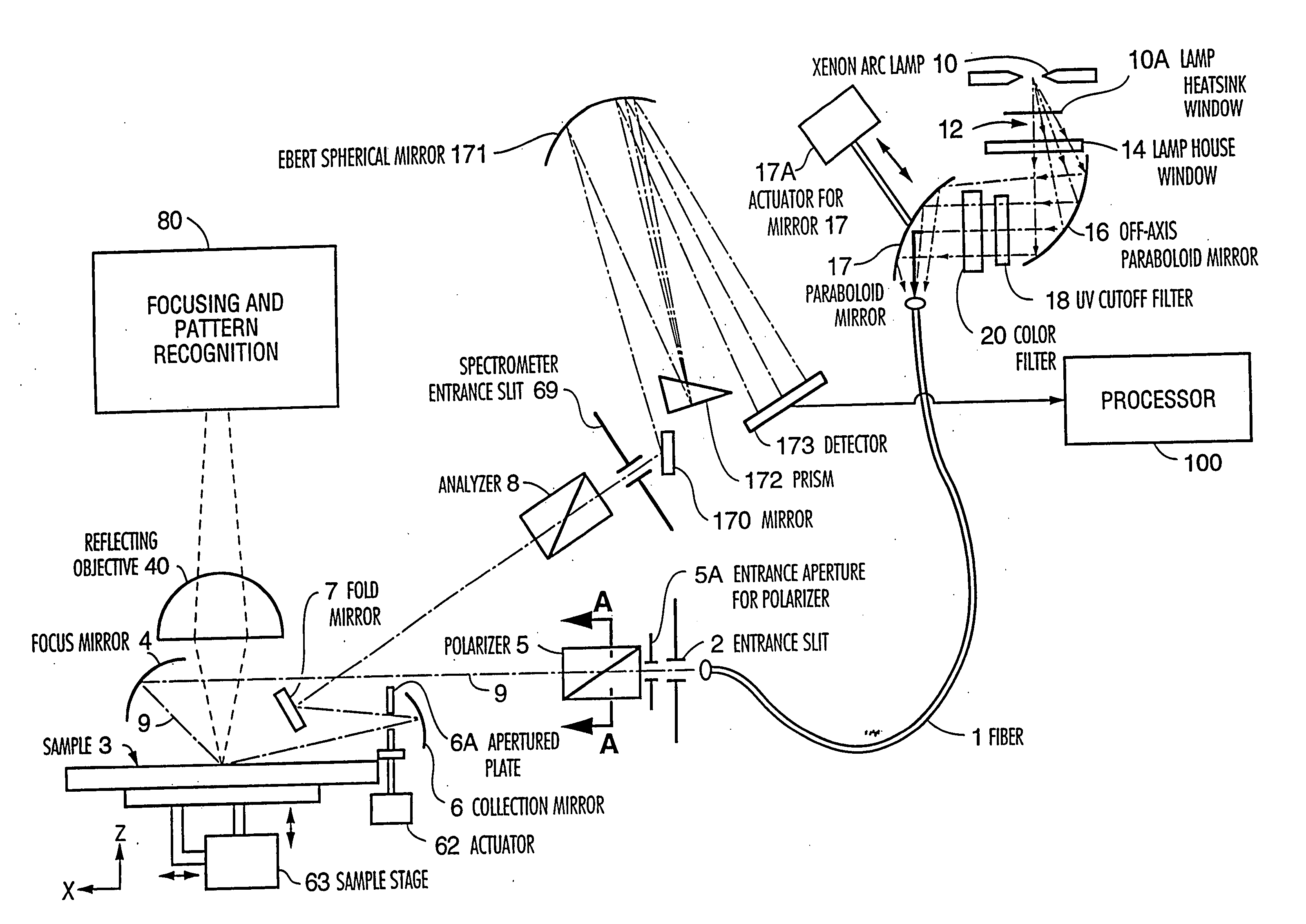
[0033] Throughout the specification, including in the claims, the phrase “incidence angle” of radiation at a surface denotes the angle between the normal to the surface and the propagation direction of the radiation. Thus, radiation with normal incidence at a sample surface has an incidence angle of zero degrees, and radiation with grazing incidence at such surface has an incidence angle substantially equal to 90°. Throughout the specification, including in the claims, the phrase “high incidence angle” denotes an incidence angle greater than 30°. Throughout the specification, including in the claims, the phrase “broadband radiation” denotes radiation whose frequency-amplitude spectrum includes two or more different frequency components. For example, broadband radiation may comprise a plurality of frequency components in the range from 230 nm to 850 nm, or a plurality of frequency components in the range from 400 nm to 700 nm.

[0034] A preferred embodiment of the focused beam spectro...


PUM


Abstract

A method and system for spectroscopic ellipsometry employing reflective optics to measure a small region of a sample by reflecting radiation (preferably broadband UV, visible, and near infrared radiation) from the region. The system preferably has an autofocus assembly and a processor programmed to determine from the measurements the thickness and/or complex refractive index of a thin film on the sample. Preferably, only reflective optics are employed along the optical path between the polarizer and analyzer, a sample beam reflects with low incidence angle from each component of the reflective optics, the beam is reflectively focused to a small, compact spot on the sample at a range of high incidence angles, and an incidence angle selection element is provided for selecting for measurement only radiation reflected from the sample at a single, selected angle (or narrow range of angles). The focusing mirror preferably has an elliptical shape to reduce off-axis aberrations in the focused beam. Some embodiments include both a spectrophotometer and an ellipsometer integrated together as a single instrument. In such instrument, the spectrophotometer and ellipsometer share a radiation source, and radiation from the source can be focused by either the spectrophotometer or the ellipsometer to the same focal point on a sample. Preferred embodiments of the ellipsometer employ a rotating, minimal-length Rochon prism as a polarizer, and include a spectrometer with an intensified photodiode array to measure reflected radiation from the sample, and a reference channel (in addition to a sample channel which detects radiation reflected from the sample).

Description

FIELD OF THE INVENTION [0001] The invention relates to methods and systems for obtaining ellipsometric and reflectance measurements of a small region of a sample over a range of UV (and preferably also visible) wavelengths, and optionally also for determining, from the measurements, the thickness and refractive index of a very thin film on the sample. The sample can be a semiconductor wafer having at least one thin layer over a silicon substrate. Preferred embodiments of the invention include both a spectrophotometer and an improved spectroscopic ellipsometer which share a common focal point on the sample and preferably a common radiation source. BACKGROUND OF THE INVENTION [0002] Among the well known nondestructive testing techniques are the techniques of spectroreflectometry and spectroscopic ellipsometry, which measure reflectance data by reflecting electromagnetic radiation from a sample. In spectroscopic ellipsometry, an incident radiation beam having a known polarization state...

Claims


Application Information

Patent Timeline
IPC IPC(8): G01N21/21
CPCG01N2021/213G01N21/211
Inventor PIWONKA-CORLE, TIMOTHY R.SCOFFONE, KAREN F.CHEN, XINGLACOMB, LLOYD J. JR.STEHLE, JEAN-LOUISZAHORSKI, DORIANREY, JOHN-PIERRE
Owner PIWONKA CORLE TIMOTHY R
Why Eureka
Try Eureka