
Metals/minerals recovery and waste treatment process

a technology for mineral recovery and waste treatment, applied in the direction of water/sludge/sewage treatment, differential sedimentation, solid separation, etc., can solve the problems of high cost of use, poor supernatant quality, and complex separation process, etc., to achieve improved flocculation efficiency, improved flocculation efficiency, and improved water dilution ratio

Inactive Publication Date: 2005-05-26
CIBA SPECIALTY CHEM WATER TRATMENTS
View PDF23 Cites 13 Cited by
  • Summary
  • Abstract
  • Description
  • Claims
  • Application Information

AI Technical Summary

Benefits of technology

[0037] An advantage of the present invention is the formation of a recycle stream having a reduced amount of suspended solids. A relatively dirty recycle stream can adversely affect the mineral processing operation and cause excessive metal / mineral losses, cause an increase in the amount of mineral processing reagents needed in the recovery process, and result in excessive non-value solids in the recovered metal / mineral.
[0038] The aqueous waste from metal / mineral processing is a slurry consisting primarily of waste mineral particles in water. In general, the aqueous mineral waste generally contains not more than 20% and usually not more than 10% total mineral solids by weight, but usually contains at least 0.1% and usually at least 0.5% by weight total mineral solids. The solids generally consist wholly or mainly of mineral fines but can include some coarser waste or some coarser mineral values, such that the coarser material can be sedimented from the waste while the fines remain in suspension. The mineral fines usually constitute at least 20% and usually at least 10% by weight of the dry matter of the waste.
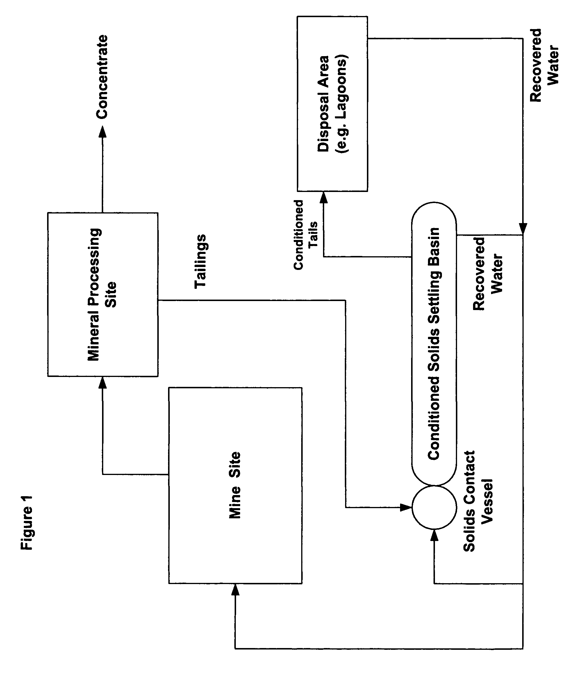
[0039] If the aqueous mineral waste contains coarse mineral values or other coarse settleable material, these materials may be sedimented from the waste as it flows through a launder towards the SCV (for instance as described in U.S. Pat. No. 5,688,404), or these values may be sedimented in a lagoon prior to the SCV treatment of the present invention. Thus the waste containing the mineral values may be directed into an entry area of a settling lagoon, and the resulting reduction in flow velocity that occurs as the waste enters the lagoon causes sedimentation of the mineral values primarily in the entry area. The mineral values can then be recovered from the base of the entry area or, if appropriate, from the base of the entire lagoon by excavation.
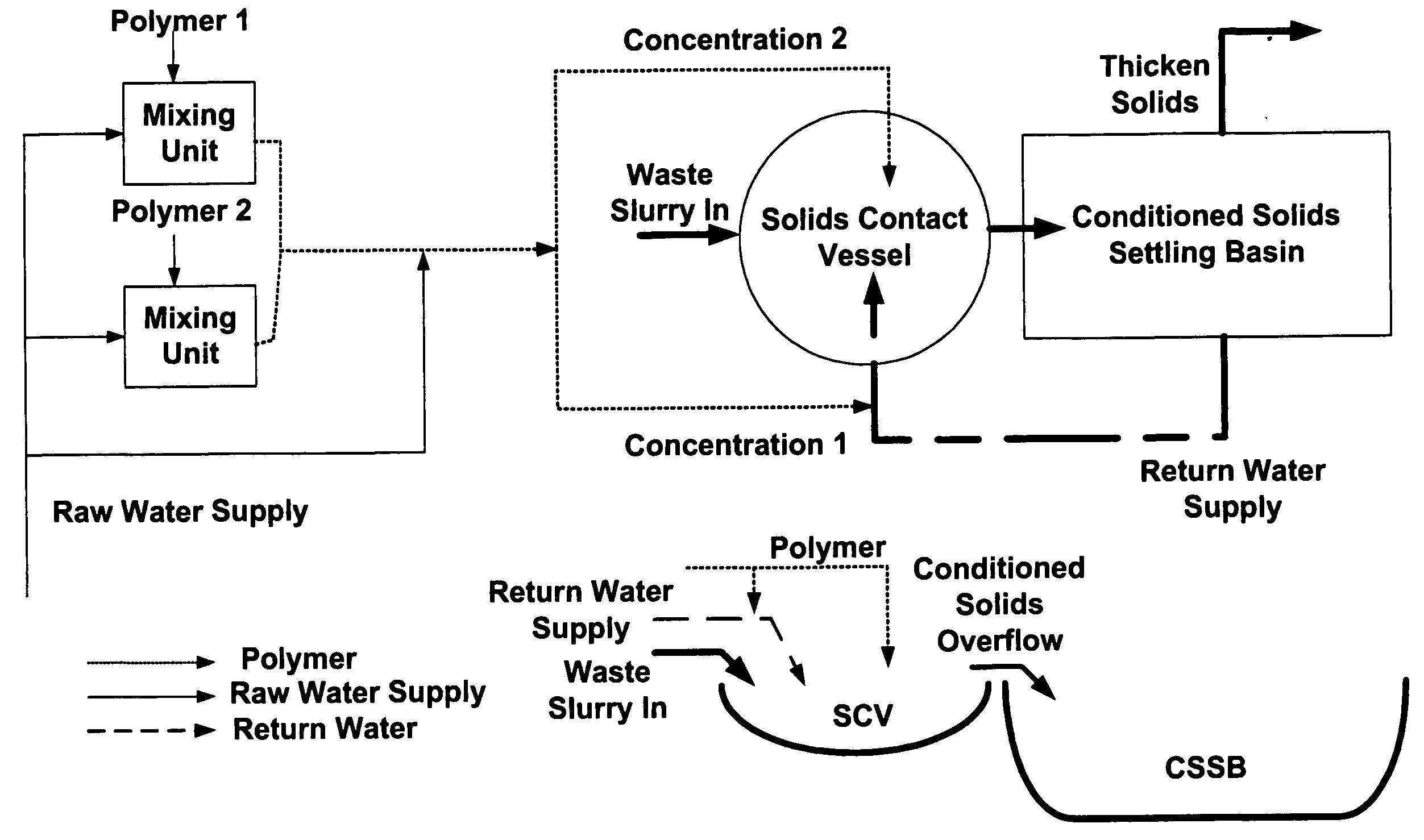
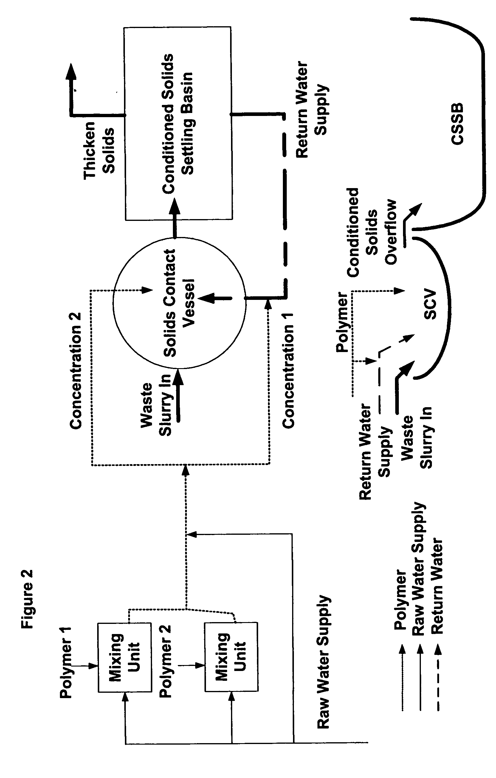
[0040] The aqueous mineral waste, optionally after preliminary sedimentation of coarse materials, then flows into a SCV that has either been formed in the ground or exists as a piece of equipment. The SCV can be located within or in the vicinity of a primary lagoon, an existing mine cut, a channel, an emergency spillway, a secondary containment area, or virgin territory. In a preferred embodiment, the SCV is located in any convenient location, such as a primary lagoon, more particularly at the base or waste entrance of a primary lagoon. The SCV may be made by excavation of, for example, a square, rectangular, circular or oval area in the ground to a sufficient depth. Optionally, the SCV may be made of a fabricated piece of equipment existing either above ground, at ground level, or below ground. If desired, the SCV can be lined in order to prevent erosion of the walls, but this is usually unnecessary.
[0041] The dimensions for the SCV in the inventive process can vary widely depending on the flow rate. Generally they comprise a depth of from about 6 to about 20 feet or deeper as convenient, preferably about 10 to about 15 feet, and an upper surface area (generally approximating a square or round area) which gives a flow rate of 0.01 to 1, preferably 0.1 to 0.5, U.S. gallons per minute per square foot of surface area. The required surface area depends on the flow rate of the waste. The SCV provides an optimum environment for the flocculant and solids contact. Once the solids have been flocculated, the SCV will feed the Conditioned Solids Settling Basin (CSSB) via a weir and / or channel.
[0042] As a result of utilizing a SCV and an associated CSSB instead of a settlement column, it is possible to generate a very large volume and a deep settlement zone very cost-effectively.

Problems solved by technology

The separation process can be very simple or very complex involving many unit processes.
Despite the numerous proposals to use flocculants, in practice it has been found that their use frequently is not cost effective.
Even when a flocculant is used to promote sedimentation and the provision of a supernatant that can be recycled, the quality of the supernatant tends to be rather poor because the supernatant tends to be contaminated with unflocculated waste particles.
Unfortunately the volume of aqueous wastes which are generated in metals and / or mineral recovery processes can be so large that it is impracticable even to contemplate the provision of column separating tanks of this type.

Method used


Image

  • Metals/minerals recovery and waste treatment process
  • Metals/minerals recovery and waste treatment process
  • Metals/minerals recovery and waste treatment process

Examples


example 1

[0091] The results detailed in this example detail how three different methods of flocculant addition perform on a sample of phosphatic clay. Each table represents use of a different flocculant product to further illustrate that the performance improvements obtained by using the dual concentration method of addition are not limited to an isolated case and that the performance benefits are achieved with each evaluation.

Flocculant; MAGNAFLOC ® 336FlocculantSupernatantAdditionDoseSettlementUnderflowTurbidity,Methodppmlbs / TRate, in / minVolume, mlNTU*Conventional20.480.2038079040.960.7820033561.445.97120179High Dilution -10.481.96220141Single1.50.723.48165102Concentration20.966.6912093High Dilution -10.488.6810082Dual1.50.7219.089059Concentration20.9647.248071

*NTU = Nephelometric Turbidity Units

[0092]

Flocculant; MAGNAFLOC ® 4240FlocculantSupernatantAdditionDoseSettlementUnderflowTurbidity,Methodppmlbs / TRate, in / minVolume, mlNTUConventional30.721.5827035440.964.1212023451.207.91110149Hi...

example 2

[0098] Using the dual addition technique described above, the following results detail the effect of applying two different flocculants blended at various ratios:

ProductSettlementUnderflowSupernatantProductCombinationDoseRate,Volume,Turbidity,ABRatio (A:B)ppmlbs / Tin / minmlNTUMAGNAFLOCDP203-100:0 1.50.634.15160184336983220.845.991501642.51.0512.99130130 0:1001.50.634.2017012720.846.621401142.51.0511.991308975:251.50.633.052207320.847.871401362.51.0514.6013010960:401.50.633.4019017120.8412.35120992.51.0517.8412010150:501.50.633.2819016420.849.691301132.51.0517.5813010240:601.50.632.9520016320.847.151501312.51.0512.981309525:751.50.634.1217014120.846.301501232.51.0511.5913092

[0099] The results below detail the conditions required to achieve a 6 in / min. settlement rate.

ProductSupernatantProductCombinationDose,UnderflowTurbidity,ABRatio (A:B)lbs / TVolume, mlNTUMagnaflocDP203-100:0 0.841501643369832 0:1000.8014411775:250.76216412160:400.68616414950:500.7216013940:600.78516113925:750.821...

example 3

[0102]

Iron Ore - Using MAGNAFLOC ® 370FlocculantSupernatantAdditionDoseSettlementUnderflowTurbidity,Methodppmlbs / TRate, in / minVolume, mlNTUConventional1.000.053.38652471.500.074.76601212.000.105.2670111High Dilution -0.500.055.9970135Single0.750.076.3670110Concentration1.000.106.807076High Dilution -0.500.056.0170124Dual0.750.077.6270102Concentration1.000.109.006556

[0103] The results in the above table indicate that the dual concentration method of addition achieves improved both settlement rate and supernatant turbidity


PUM

PropertyMeasurementUnit
Fractionaaaaaaaaaa
Fractionaaaaaaaaaa
Fractionaaaaaaaaaa

Abstract

A metals / minerals recovery and waste treatment process comprising a main separation stage in which a metal / mineral-bearing ore is slurried with water and separated into an enriched fraction and an aqueous metal / mineral waste fraction, and a waste sedimentation stage in which the aqueous metal / mineral waste fraction is sedimented in one or more settling lagoons to provide a thickened sediment layer and supernatant; and the waste sedimentation stage comprises feeding the aqueous metal / mineral waste into a solids contact vessel or other flocculating chamber, wherein the aqueous metal / mineral waste is diluted with water containing one or more flocculant(s) at more than one concentration, one of which concentrations is at least 10 times higher than the other, within the SCV, flocculating the diluted aqueous waste, and sedimenting the diluted and flocculated aqueous waste to provide a liquid supernatant layer and a pumpable thickened sediment layer in a settling basin.

Description

[0001] This application claims the benefit of Application No. 60 / 523,814, filed Nov. 20, 2003.BACKGROUND [0002] This invention relates to a metals and / or minerals recovery and waste treatment process that comprises a main separation stage and a waste sedimentation stage. The objective is to treat waste sediment from a metals and / or minerals processing facility in a novel and efficient manner. [0003] Flocculation is the aggregation of single particles or small groups of particles, into multi-particle aggregates or ‘flocs’. The technique is used in many industrial processes to enhance solid-liquid separation. [0004] In terms of definition it is necessary to make a distinction between coagulation and flocculation, since both involve particle aggregation but by different mechanisms. The process of coagulation involves particle aggregation by surface charge neutralization, thereby overcoming the repulsive potential barrier between particles. Particle surface charge is invariably negative...

Claims


Application Information

Patent Timeline
IPC IPC(8): B03D3/06C02F1/56
CPCB03D3/06C02F1/56Y10S210/907C02F2103/10C02F2101/105Y02P10/20
Inventor DWYER, PATRICK JOSEPH
Owner CIBA SPECIALTY CHEM WATER TRATMENTS
Learn More