Glass fixture-joined glass article and joint structure using this

a glass fixture and glass article technology, applied in the field of glass articles, can solve the problems of cracks at the surface of glass sheets, difficult to ensure the bond strength of metal terminals, and affect the appearance of electroconductive coating films, so as to improve the bond strength and not only the appearance

Active Publication Date: 2005-05-26
NIPPON SHEET GLASS CO LTD
View PDF0 Cites 54 Cited by
  • Summary
  • Abstract
  • Description
  • Claims
  • Application Information

AI Technical Summary

Benefits of technology

[0009] The first problems can be solved by an addition of Ag to a Sn-based lead-free solder alloy. The addition of Ag improves not only the appearance but also the bond strength. From a first aspect, the present invention provides a glass article with a metal member joined thereto in which an electroconductive coating film is formed on at least a part of

Problems solved by technology

However, when a metal terminal is joined to a glass sheet using a lead-free solder alloy, particularly, a Sn-based lead-free alloy, the following problems occur.
First, the electroconductive coating film may melt and flow into the soldered junction, which may impair the appearance of the electroco

Method used


Image

  • Glass fixture-joined glass article and joint structure using this
  • Glass fixture-joined glass article and joint structure using this
  • Glass fixture-joined glass article and joint structure using this

Examples


example 1

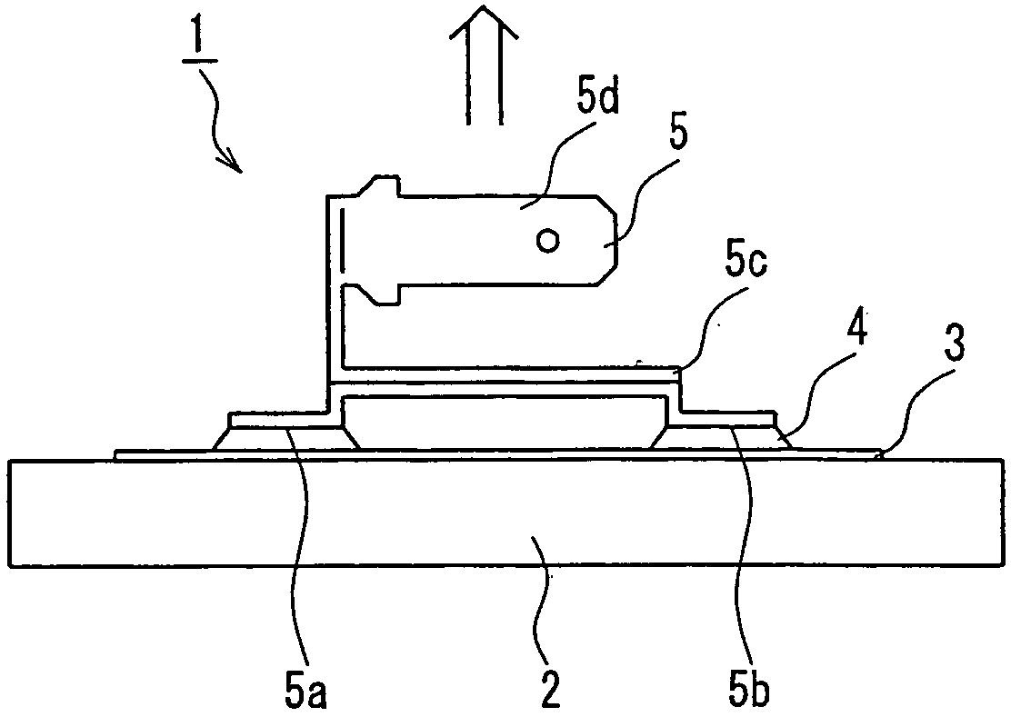
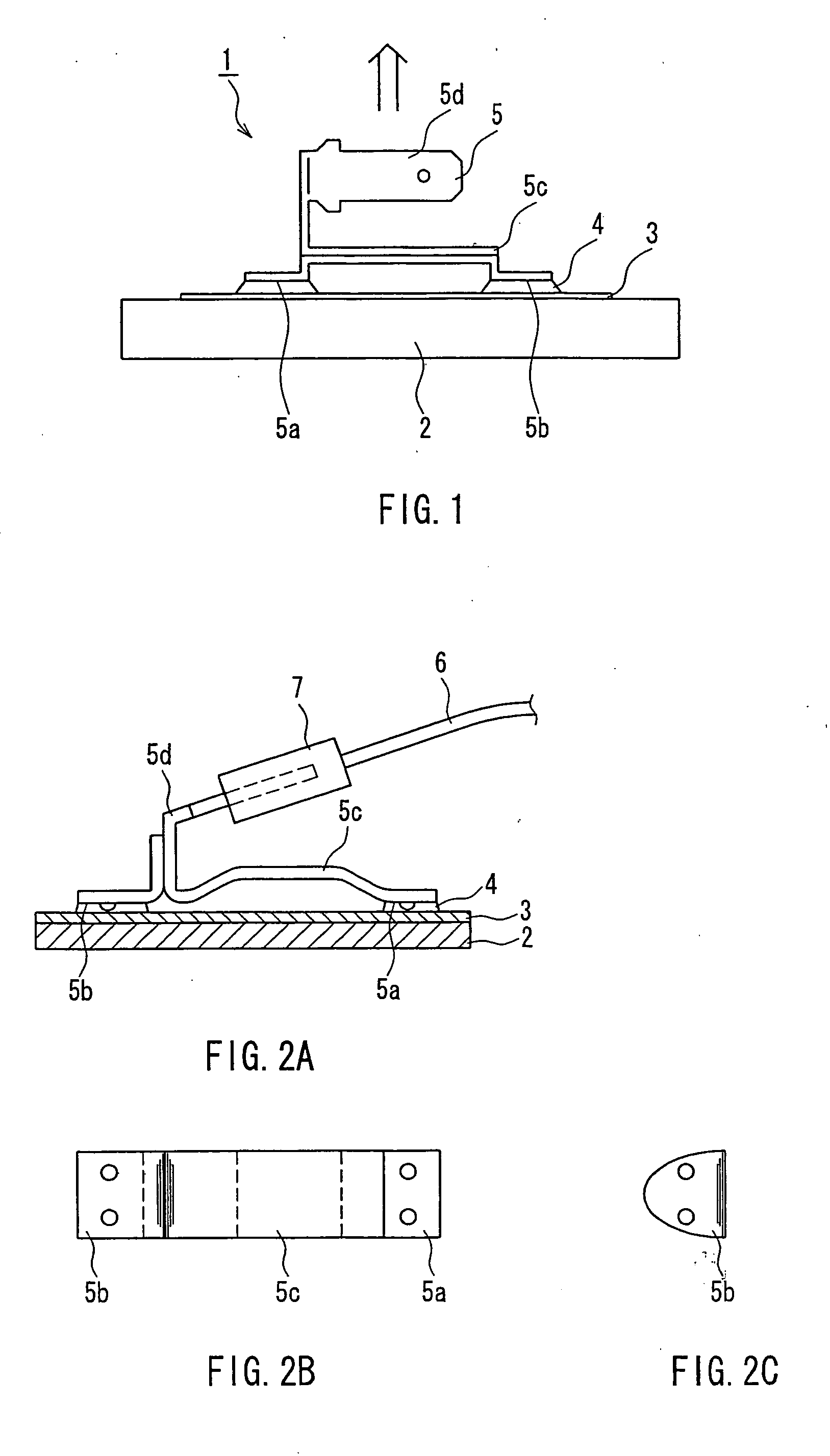
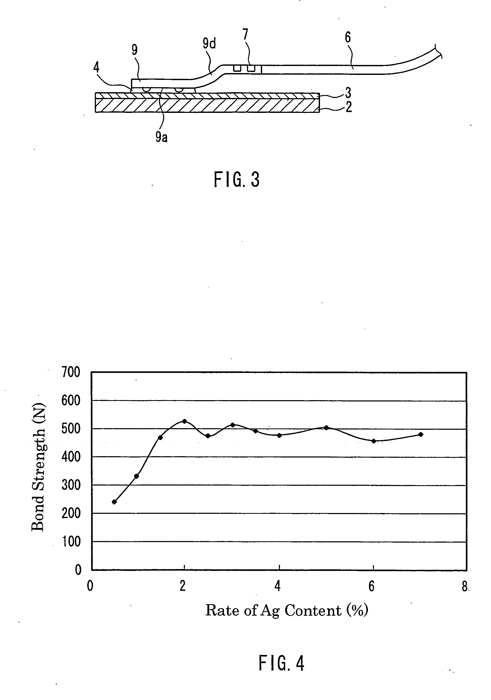
[0035] The same junction structures as that shown in FIG. 1 were produced. In each of them, soda-lime silica glass having a thickness of 3.1 mm was used for the glass sheet 2, a Sn—Ag alloy whose Ag content is shown in Table 1 was used as the lead-free solder alloy 4, and a terminal formed of a Cu metal sheet was used as the metal terminal 5. The areas of the two joining planes of the metal terminal 5 are set to be equal (a ratio of 1:1) to each other and to sum up to 56 mm2. The electroconductive coating film 3 was formed by screen-printing an Ag paste containing about 80 mass % of Ag particles, about 5 mass % of a glass frit, and about 15 mass % of an organic solvent, drying it, and further baking it at about 700° C.

[0036] The lead-free solder alloy was applied to the joining planes of the metal terminal beforehand. The soldering was carried out by applying a flux to the solder alloy, pressing the joining planes of the metal terminal onto the electroconductive coating film, and p...

example 2

[0041] Samples were obtained in the same manner as in Example 1 except that a Sn—Ag alloy was used that contains 98 mass % of Sn and 2 mass % of Ag, and the total area of the joining planes was set at the values shown in Table 2.

[0042] With respect to each sample thus obtained, its bond strength was measured in the same manner as in Example 1. The results are shown in Table 2.

[0043] In all the samples, rupture of the junction took place not at the soldered junction but inside the glass.

TABLE 2Total Area ofJoining PlanesBond StrengthSamples(mm2)(N)2A28522.32B35519.52C42727.92D49591.82E56503.1

[0044] As is apparent from FIG. 5 showing the relationship between the total area of joining planes (joining area) and the bond strength, the bond strength degrades both in the case where the joining area is too large and where it is too small. Thus, in order to improve the bond strength in the junction structure in which the terminal having a plurality of joining planes is fixed with a “hard...

example 3

[0045] Samples were obtained in the same manner as in Example 1 except that the amount of the lead-free solder alloy 4 provided on the respective joining planes and the total area of the joining planes were set at values shown in Table 3. With respect to each of n pieces of samples thus obtained, a thermal test was carried out through predetermined temperature cycling, and the state of the glass surface was checked visually every 100 cycles after 200 cycles. The temperature cycling was set to include a period of retention for 30 minutes at −30° C., a period of raising temperature to 80° C. in three minutes, a period of retention in this state for 30 minutes, and a period of decreasing temperature to −30° C. in three minutes, and thus the thermal cycle test was carried out. The results are shown in Table 3.

[0046] In Samples 3A to 3D and 3F to 3G, no cracks occurred in the glass even when the above-mentioned thermal cycle was repeated 500 times. In Sample 3A, the bond strength determ...


PUM

PropertyMeasurementUnit
Percent by massaaaaaaaaaa

Abstract

The present invention is intended to provide a glass article with a metal member joined thereto in which an electroconductive coating film is formed on at least a part of the surface of the glass article by baking a silver paste that includes Ag particles and a glass frit, a joining plane of the metal member is fixed onto the electroconductive coating film with a lead-free solder alloy containing Sn as a main component, and the lead-free solder alloy contains at least 1.5 mass % of Ag, which prevents the appearance of the electroconductive coating film and the bonding strength from degrading. Furthermore, in the present invention, when using a metal member having at least two joining planes, the total area of the joining planes is set within a range of 37 mm2 to 50 mm2, which allows high bonding strength between the glass article and metal member to be maintained while using the lead-free solder alloy. Moreover, in the present invention, the volume of the lead-free solder alloy to be provided on each joining plane is set to be 1.0 to 2.0 times the product of the area of the joining plane concerned and the thickness of the lead-free solder alloy, which prevents cracks from occurring in the glass article.

Description

TECHNICAL FIELD [0001] The present invention relates to a glass article with a metal member joined thereto, and a structure of joining a glass article and a metal member together. Particularly, the present invention relates to an adequate junction made between a glass article and a metal member using a lead-free solder alloy. BACKGROUND ART [0002] In order to ensure the driver's view, electroconductive lines (heating wires) are formed as a defogger on the surface of a glass sheet to be used for a rear window of a car in some cases. The defogger is supplied with an electric current through a feeding metal terminal. This metal terminal is provided on a bus bar connected to the defogger. In some cases, a glass antenna may be used for the rear and side windows of a car. In the case of using the glass antenna, electroconductive lines are formed, on the surface of a glass sheet, in a pattern (an antenna pattern) corresponding to the wavelength to be received. A metal terminal also is prov...

Claims


Application Information

Patent Timeline
IPC IPC(8): B23K1/00B23K1/20B23K35/26H01R4/02H01R4/04H01R4/62H01R4/64H05B3/84
CPCB23K1/0008B23K1/20B23K35/262B23K2203/16B23K2203/18H01R4/02H05B2203/016H01R4/62H01R4/625H01R4/64H01R2201/02H01R2201/26H05B3/84H01R4/04B23K2103/54B23K2103/12B23K2103/16B23K2103/18
Inventor OKAJIMA, ICHIROWATANABE, HIDEKIYAMADA, KAZUO
Owner NIPPON SHEET GLASS CO LTD
Why Eureka
Try Eureka