Optical information medium

a technology of optical information and optical coating, applied in the field of optical coating, can solve the problems of poor durability and tend to be expensive to produce, and achieve the effects of superior scratch resistance and abrasion resistance, excellent anti-staining properties and lubricity

Inactive Publication Date: 2005-05-26
TDK CORPARATION
View PDF9 Cites 34 Cited by
  • Summary
  • Abstract
  • Description
  • Claims
  • Application Information

AI Technical Summary

Benefits of technology

[0029] The present invention provides an optical information medium in which the recording and / or reproducing beam incident side surface displays excellent anti-staining properties and lubricity, as well as superior scratch resistance and abrasion resistance.

Problems solved by technology

However, such conventional hard coat materials as described above suffer not only from a variety of physical problems such as poor durability of the anti-staining property or insufficient hardness, but also tend to be expensive to produce.

Method used


Image

  • Optical information medium
  • Optical information medium

Examples


example 1

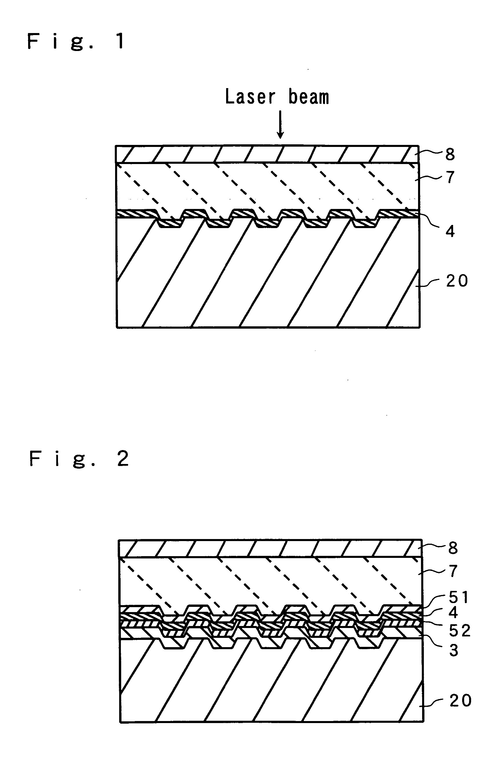
[0114] An optical recording disk sample with the layer structure shown in FIG. 2 was produced as follows.

[0115] Using a disk shaped supporting substrate (20) (formed from polycarbonate, diameter 120 mm, thickness 1.1 mm) in which information recording grooves had been formed, sputtering was used to form a reflective layer (3) of thickness 100 nm comprising Al98Pd1Cu1 (atomic ratio) on the groove-side surface of the substrate. The depth of the grooves, which is represented by light-path length at a wavelength λ=405 nm, was set into λ / 6. The recording track pitch in the groove-recording scheme was set into 0.32 μm.

[0116] Subsequently, sputtering with an Al2O3 target was used to form a second dielectric layer (52) of thickness 20 nm on the surface of the reflective layer (3). Sputtering using an alloy target comprising a phase-changing material was then used to form a recording layer (4) of thickness 12 nm on the surface of the second dielectric layer (52). The composition (atomic ra...

example 2

[0122] In the formation of the hard coat layer (8), with the exceptions of adding 3 parts by weight of 1-hydroxycyclohexyl phenyl ketone as a photopolymerization initiator to the hard coat agent, and conducting the curing process by irradiation with ultraviolet rays, under the conditions described below, instead of by irradiation with electron rays, a disk sample was prepared in the same manner as the example 1.

Type: high pressure mercury lamp (160 W / cm), total energy: 3 J / cm2, separation between the lamp and the applied layer: 11

example 3

[0123] With the exception of replacing the 13 parts by weight of the fluorine-containing block copolymer 1 in the composition of the hard coat agent with 3 parts by weight of MODIPER-F600 (manufactured by NOF Corporation, nonvolatile content: 100%), a disk sample was prepared in the same manner as the example 2.


PUM

PropertyMeasurementUnit
particle sizeaaaaaaaaaa
wavelengthaaaaaaaaaa
thicknessaaaaaaaaaa

Abstract

The present invention provides an optical information medium in which the recording and/or reproducing beam incident side surface displays excellent anti-staining properties and lubricity, as well as superior scratch resistance and abrasion resistance. An optical information medium comprising a film element composed of one or more layers including at least a recording layer (4) or a reflective layer, on a supporting substrate (20), wherein at least one of the supporting substrate (20)-side surface and the film element-side surface is formed of a hard coat layer (8) comprising a cured product of the hard coat agent composition comprising a fluorine-containing block copolymer (A) and an active energy ray-curable compound (B).

Description

BACKGROUND OF THE INVENTION [0001] 1. Field of the Invention [0002] The present invention relates to an optical information medium such as a read-only optical disk, an optical recording disk or a magneto-optical recording disk, and more specifically to an optical information medium in which the recording and / or reproducing beam incident side surface displays excellent anti-staining properties and lubricity, as well as superior scratch resistance and abrasion resistance. [0003] 2. Disclosure of the Related Art [0004] On the surfaces of optical disks such as read-only optical disks, optical recording disks and magneto-optical recording disks, the stains from various stain materials and the adhesion of fingerprints are caused during use. These stains and adhesion fingerprints are undesirable, and accordingly, the surfaces of optical disks may be subjected to a suitable surface treatment to improve the anti-staining property, reduce the adhesion of fingerprints, and improve the ease wit...

Claims


Application Information

Patent Timeline
Patent Type & Authority Applications(United States)
IPC IPC(8): C08K5/00C03C17/00C03C17/34C08F290/12C08F299/00C08K7/18C08L101/04G11B7/24G11B7/24056G11B7/254G11B7/2542G11B7/257
CPCC03C17/007Y10T428/21C03C17/3405C03C2217/445C03C2217/475C03C2217/478C08F290/12C08F299/00G11B7/2534G11B7/2542G11B7/2585G11B2007/2431G11B2007/24312G11B2007/24314G11B2007/24316G11B2007/25708G11B2007/25715C03C17/34
Inventor ITOH, HIDETAKETANAKA, KAZUSHIHAYASHIDA, NAOKI
Owner TDK CORPARATION
Why Eureka
Try Eureka