Gas barrier film and method for producing the same

a technology of gas barrier film and film, applied in the field of gas barrier film, can solve the problems of degrading display quality, plastic base materials have drawbacks, and their gas barrier property is inferior to that of glass base materials, and achieve the effect of superior gas barrier property

Inactive Publication Date: 2005-05-26
FUJIFILM HLDG CORP +1
View PDF2 Cites 49 Cited by
  • Summary
  • Abstract
  • Description
  • Claims
  • Application Information

AI Technical Summary

Benefits of technology

[0012] The present invention was accomplished in view of the aforementioned problems, and an object of the present invention is to provide a gas barrier film that can exhibit superior gas barrier property when it is used in image display devices such as liquid crystal display devices and organic EL devices and a method for producing such a gas barrier film. Another object of the present invention is to provide an organic EL device utilizing such a gas barrier film.

Problems solved by technology

However, plastic base materials have a drawback that their gas barrier property is inferior to that of glass base materials.
If a base material having poor gas barrier property is used, water vapor and air permeate the material to, for example, degrade liquid crystals in a liquid crystal cell, form display defects and thereby degrade display quality.
However, in these methods for forming a thin film, an organic substance blown as a vapor of a high temperature condenses on a film and form a thin film, and the film is temporarily heated and causes partial deformation.
As a result, the subsequent lamination step becomes uneven, and thus the methods have a problem that they cannot provide sufficient barrier ability.
Moreover, in these methods for forming a thin film, the number of the lamination step increases, and thus they have a problem of high cost.
Furthermore, when a surface of a plastic substrate showing high water absorption is treated, the absorbed moisture is vaporized, thus it requires long time to obtain vacuum, and therefore there is also a problem that the processing cost becomes high.
On the other hand, such methods for forming a semiconductor layer as described above use complicated configurations and apparatuses and require high cost, and therefore heat resistance for a temperature of 300° C. to 350° C. or higher is desired for plastics substrates.
U.S. Pat. No. 6,492,026 discloses a heat-resistant substrate having a barrier stack consisting of at least one inorganic layer and at least one polymer layer but it fails to show sufficient heat resistance.

Method used


Image

  • Gas barrier film and method for producing the same
  • Gas barrier film and method for producing the same
  • Gas barrier film and method for producing the same

Examples


example 1

[0130] In Example 1, a polyimide film (UPILEX-R, Ube Industries) having a thickness of 100 μm (Tg: 285° C.) was used as a plastic base material for the present invention. In the comparative example, a polyethersulfone (PES) film having a thickness of 100 μm (Tg: 220° C.) and a ZEONOA film having a thickness of 100 μm (Tg: 160° C.) were used as a plastic base material.

[0131] 1. Preparation of inorganic oxide layer

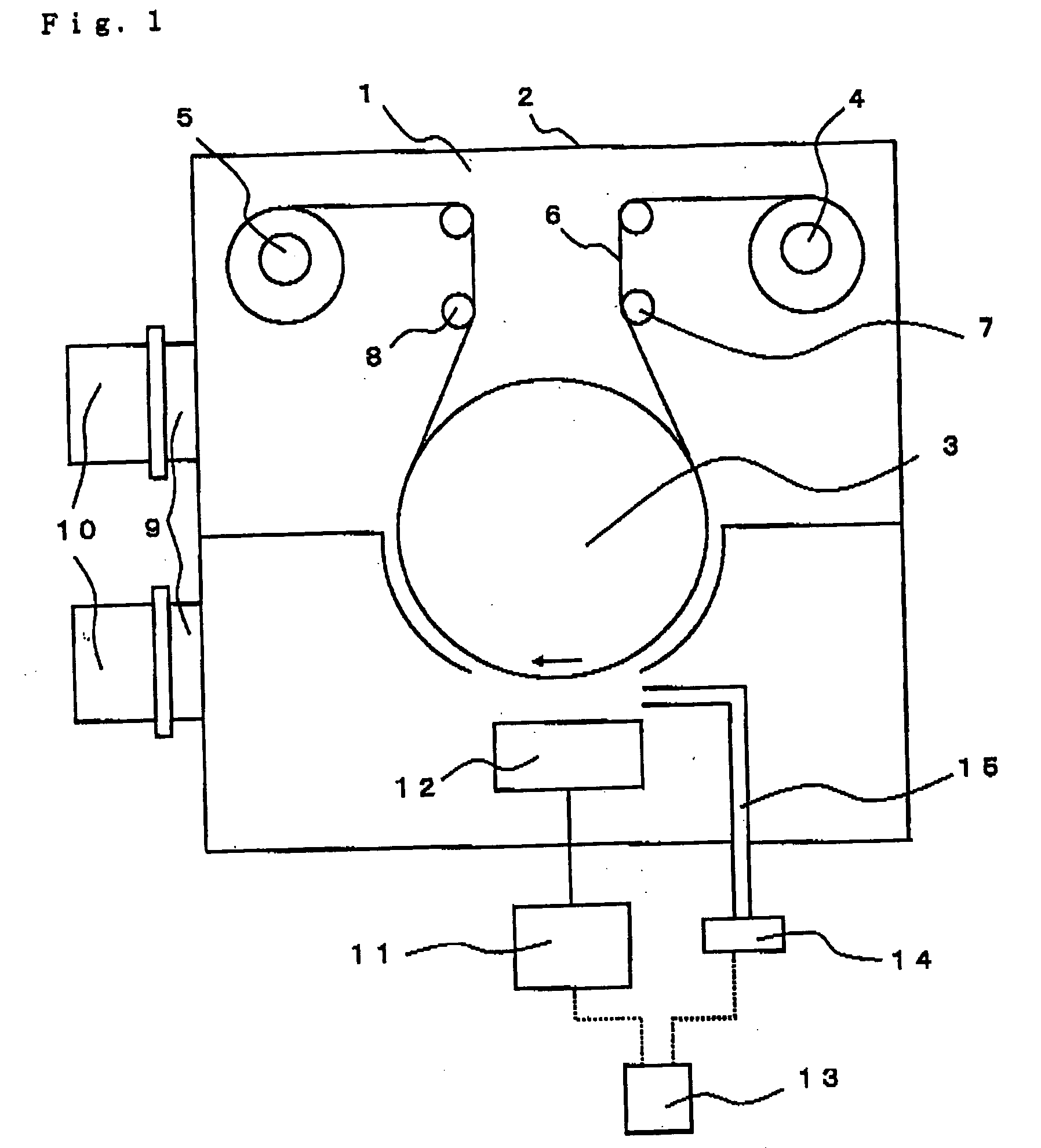
[0132] As shown in FIG. 1, an inorganic layer was prepared by using a roll-to-roll type sputtering apparatus 1. This apparatus 1 had a vacuum-chamber 2, and a drum 3 for cooling a plastic film (base material) 6 by contact on the surface was disposed at the center of the chamber. Further, a feeding roller 4 and rolling-up roller 5 for winding the plastic film 6 were disposed in the aforementioned vacuum chamber 2. The plastic film 6 wound around the feeding roller 4 was wound around the drum 3 via a guide roller 7, and further the plastic film 6 was wound around a roller 5 ...

example 2

[0144] 1. Preparation of plastic substrate

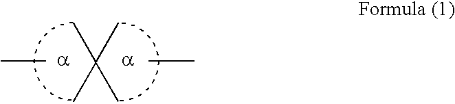
[0145] A resin represented by the formula (1) synthesized as follows (C-3, Tg: 270° C.) was dissolved in dichloromethane at a concentration of 15 weight % and cast on a stainless steel band by the die coating method. Then, the first film was stripped off from the band, and dried until the remaining solvent concentration became 0.08 weight %. Then, the film was trimmed and knurled for the both edges, and the film was rolled up to prepare Film 2A having a thickness of 100 μm.

Synthesis Example of C-3

[0146]

[0147] In an amount of 235.59 g (646.8 mmol) of M-100, 9.171 g (33 mmol) of tetrabutylammonium chloride, 2805 mL of dichloromethane and 2475 mL of water were put into a reaction vessel provided with a stirrer and stirred at 300 rpm on a water bath under a nitrogen flow. After 30 minutes, 134.05 g (660 mmol) of terephthaloyl chloride was added as powder and washed away with 330 mL of dichloromethane. After 10 minutes, a solution obtained by ...

example 3

[0166] Films 3A to 3G were prepared by laminating one inorganic layer consisting of inorganic oxide and one organic layer consisting of an acrylate resin on Film 2A to 2D prepared in Example 2 according to the method described in International Patent Application Laid-open in Japanese No. 2002-532850. Then, water vapor permeability was measured at 45° C. and 100% of relative humidity and evaluated. The results of measured water vapor permeability are shown in Table 3.

[0167] The gas barrier film disclosed in International Patent Application Laid-open in Japanese No. 2002-532850 was prepared, and water vapor permeability thereof was measured in the same manner as in Example 3. The result of measured water vapor permeability is shown in Table 3.

TABLE 3Water vaporpermeabilityFilm(g / m2 · day)Remarks3A0.02Invention3B0.01Invention3C0.03Invention3D0.02Invention3E0.30Comparative3F0.20Comparative3G0.04InventionPET*1)0.57Comparative

*1Film described in International Patent Application Laid-op...


PUM

PropertyMeasurementUnit
glass transition temperatureaaaaaaaaaa
temperatureaaaaaaaaaa

Abstract

Disclosed is a gas barrier film alternately comprising at least one inorganic layer and at least one organic layer on a resin base material having a glass transition temperature of 250° C. or higher. The gas barrier film can exhibit superior gas barrier property when it is used in image display devices such as liquid crystal display devices and organic EL devices.

Description

BACKGROUND OF THE INVENTION [0001] 1. Field of the Invention [0002] The present invention relates to a gas barrier film having superior gas barrier performance and a method for producing the same as well as an organic electroluminescence device (henceforth referred to as “organic EL device”) utilizing the gas barrier film. More precisely, the present invention relates to a gas barrier film suitable as a substrate of various kinds of devices and a method for producing the same, as well as a flexible organic EL device utilizing the gas barrier film. [0003] 2. Description of the Background [0004] Conventionally, gas barrier films prepared by forming a thin film of metal oxide such as aluminum oxide, magnesium oxide or silicon oxide on a surface of a plastic substrate or film have been widely used in packaging of articles which require shielding of various gases such as water vapor and oxygen, and packaging use for preventing deterioration of food, industrial materials, medical supplies...

Claims


Application Information

Patent Timeline
Patent Type & Authority Applications(United States)
IPC IPC(8): B32B1/08B32B27/08B32B27/36
CPCB32B27/08Y10T428/31551Y10T428/31786Y10T428/31598Y10T428/31765Y10T428/31725Y10T428/31721Y10T428/31507
Inventor NARUSE, HIDEAKISAKURAI, SEIYA
Owner FUJIFILM HLDG CORP
Why Eureka
Try Eureka