
Use of graphite foam materials in pumped liquid, two phase cooling, cold plates

a technology of graphite foam and pumped liquid, which is applied in the direction of regenerative heat exchangers, stationary tubular conduit assemblies, combustion processes, etc., can solve the problems of damage to electrical or electronic devices, high temperature and/or large flow rate, and the inability to use sensible heating of fluid to remove heat from electrical and electronic components, etc., to achieve high thermal conductivity of ligaments, increase available surface area, and high heat transfer surface efficiency

Inactive Publication Date: 2005-06-09
THERMAL FORM & FUNCTION
View PDF8 Cites 11 Cited by
  • Summary
  • Abstract
  • Description
  • Claims
  • Application Information

AI Technical Summary

Benefits of technology

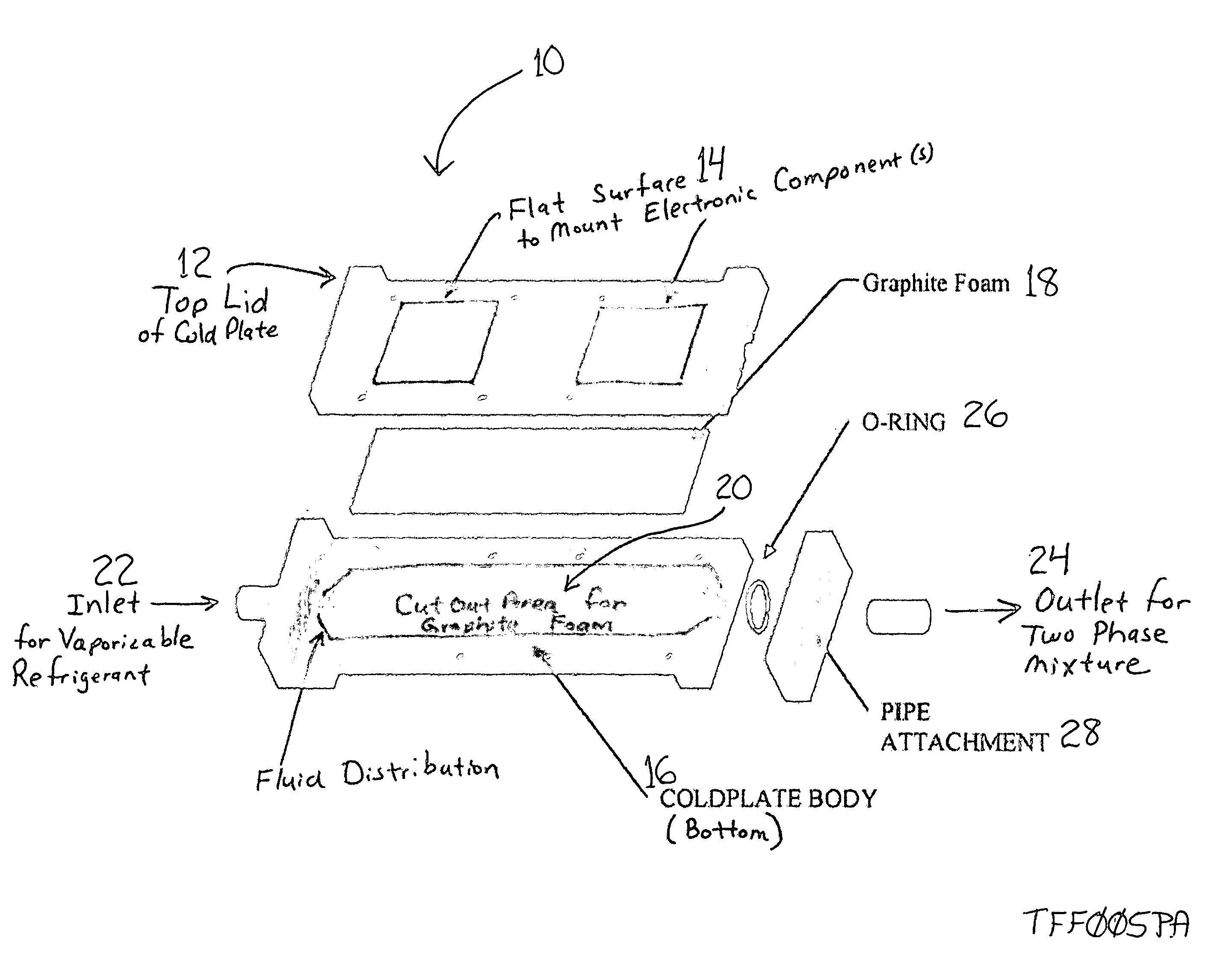
[0011] In accordance with one aspect of the present invention, a liquid refrigerant pump circulates refrigerant to cold plate / evaporators which are in thermal contact with the electrical or electronic component to be cooled. The liquid refrigerant is then partially or completely evaporated by the heat generated by the component. The vapor is condensed by a conventional condenser coil, and the condensed liquid, along with any unevaporated liquid, is returned to the pump. By replacing or adding to a convoluted fin structure in a two phase cold plate with a graphite foam material, the available surface area is increased many times over that of the fin structure. Since the graphite foam has relatively high thermal conductivity of the ligament structure in the open cell foam, the fin efficiency of the heat transfer surface remains high. Also, due to the open nature of the graphite foam, the permeability of liquids and vapor through the foam is high, allowing for low pressure loss while still maintaining sufficient two phase flow to carry heat away from the electronics.
[0012] Accordingly, it is an object of the present invention to provide cooling to electrical and electronic components. It is a further object of the present invention to provide such cooling by increasing the surface area for heat transfer within the cold plate structure, while still allowing for flow of both liquid and vapor through the structure to carry away the heat generated by the electronics.

Problems solved by technology

This method of using the sensible heating of a fluid to remove heat from electrical and electronic components is limited by the thermal capacity of the single phase flowing fluid.
This creates high temperatures and / or large flow rates to cool high power microelectronic devices.
High temperatures may damage the electrical or electronic devices, while large flow rates require pumps with large motors which consume parasitic electrical power and limit the application of the cooling system.
Large flow rates may also cause erosion of the metal in the cold plate due to high fluid velocities.
This method of removing heat is limited by the ability of the wick structure to transport fluid to the evaporator.
At high thermal fluxes, a condition known as “dry out” occurs where the wick structure cannot transport enough fluid to the evaporator and the temperature of the device will increase, perhaps causing damage to the device.
Finally, heat pipes cannot transport heat over long distances to remote dissipaters due once again to capillary pumping limitations.
Yet another method which is employed when direct air-cooling is not practical uses the well-known vapor compression refrigeration cycle.
However, this method suffers from some major disadvantages which limit its practical application in cooling electrical and electronic devices.
First, there is the power consumption of the compressor.
In high thermal load applications the electric power required by the compressor can be significant and exceed the available power for the application.
Another problem concerns operation of the evaporator (cold plate) below ambient temperature.
In this case, poorly insulated surfaces may be below the dew point of the ambient air, causing condensation of liquid water and creating the opportunity for short circuits and hazards to people.
This can cause damage and shorten the life of the compressor.
This is yet another disadvantage of vapor compression cooling of components.
However, there is a limit to the surface area which can be made by forming metal into a convoluted fin shape.
This area is even more limited if the convoluted fin needs to be lanced and offset.
With electronics becoming more powerful and smaller, the heat flux density of the silicon will soon increase to a point where convoluted fin structures in a two phase cold plate may not be able to remove the heat fast enough to keep the junction temperatures within acceptable limits.
Increasing the surface area and maintaining high velocities for high heat transfer coefficients using convoluted fin structures is difficult and is limited by the ability to form compact fin structures.

Method used


Image

  • Use of graphite foam materials in pumped liquid, two phase cooling, cold plates
  • Use of graphite foam materials in pumped liquid, two phase cooling, cold plates

Examples


Embodiment Construction

[0015] The present invention relates to cooling electronic components, including at least microprocessor semiconductors and power semiconductors, using a pumped liquid two phase cooling system, such as is described and claimed in U.S. Pat. No. 6,519,955, totally incorporated herein by reference. Specifically, the present invention is an improvement to the cold plate portion of the system which absorbs heat directly from the electronics to be cooled. The purpose of the present invention is to increase the surface area for heat transfer within the cold plate structure with a high thermal conductivity foamed graphite material, while still allowing for flow of both liquid and vapor through the structure to carry away the heat generated by the electronics.

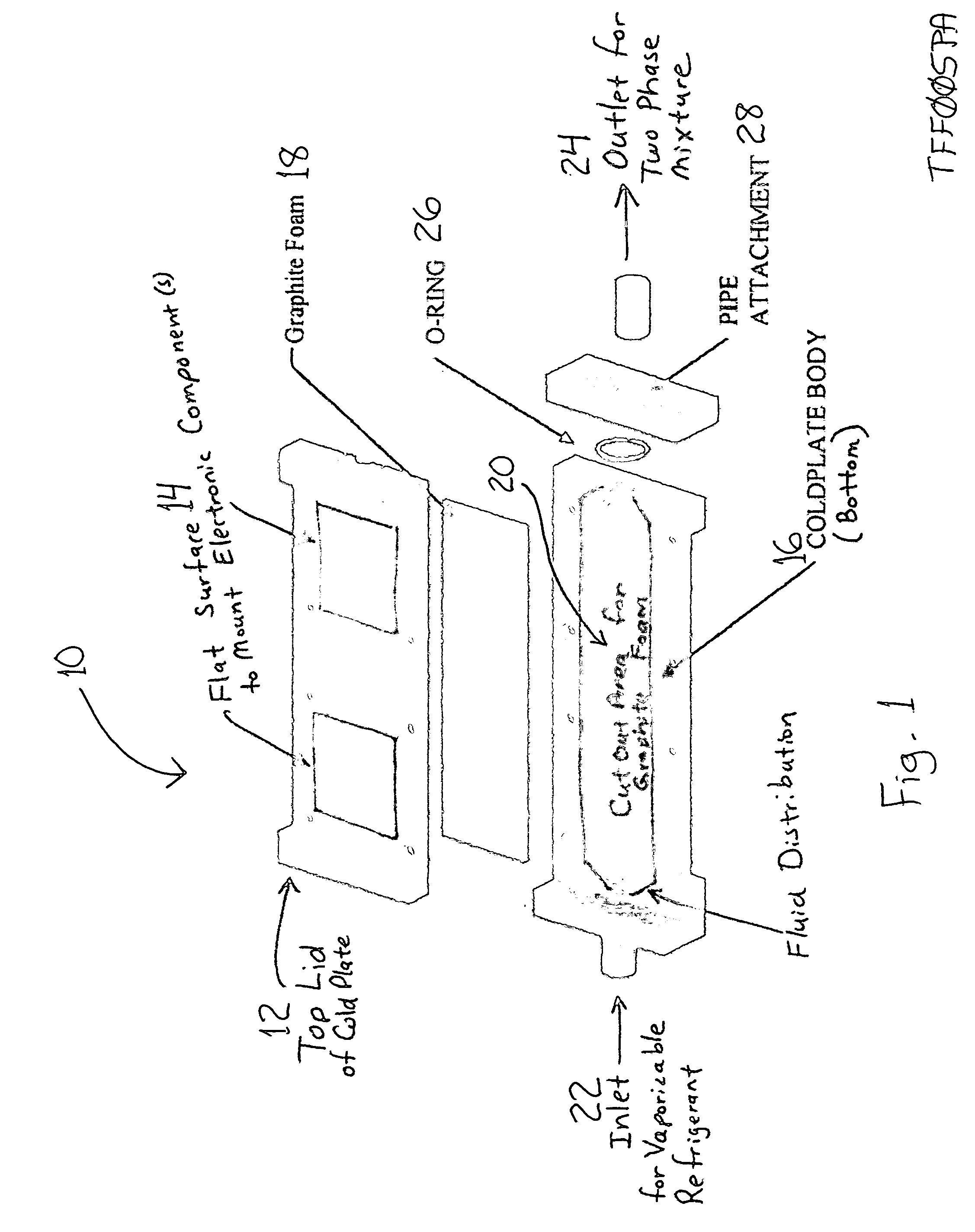
[0016] Referring now to FIG. 1, there is illustrated a two phase cold plate assembly 10 such as is used in a pumped refrigerant forced convection cooling system for removing heat from electronic systems. The present invention incorpora...


PUM

PropertyMeasurementUnit
surface areaaaaaaaaaaa
structureaaaaaaaaaa
power densitiesaaaaaaaaaa

Abstract

An improved cooling system provides cooling away from the surface of electrical and electronic components, by providing an available heat transfer surface area many times greater than that of a convoluted fin structure. The component to be cooled is in thermal contact with a cold plate evaporator device, and a graphite material is associated with the cold plate device. Refrigerant is circulated through the graphite material and the cold plate evaporator device, and the liquid refrigerant is at least partially evaporated by the heat generated by the component. Due to the open nature of the graphite material, the permeability of liquids and vapors is high, allowing for low pressure loss while still maintaining sufficient two phase flow to carry heat away from the electronics.

Description

RELATED APPLICATIONS [0001] This is a regularly filed application, based on provisional application Ser. No. 60 / 506,347, filed Sep. 26, 2003.TECHNICAL FIELD [0002] The present invention relates to cooling of electrical and electronic components, and more particularly, to use of graphite foam materials in a pumped liquid two phase cooling system having one or more cold plate / evaporators in thermal contact with the electrical or electronic components to be cooled. BACKGROUND OF THE INVENTION [0003] Electrical and electronic components (e.g. microprocessors, IGBT's, power semiconductors etc.) are most often cooled by air-cooled heat sinks with extended surfaces, directly attached to the surface to be cooled. A fan or blower moves air across the heat sink fins, removing the heat generated by the component. With increasing power densities, miniaturization of components, and shrinking of packaging, it is sometimes not possible to adequately cool electrical and electronic components with h...

Claims


Application Information

Patent Timeline
Patent Type & Authority Applications(United States)
IPC IPC(8): F23L15/02F28D17/00F28F13/00F28F21/02H01L23/373H01L23/427H05K7/20
CPCF28F13/003F28F21/02H01L23/3733H01L23/427H01L2924/0002H01L2924/00
Inventor MARSALA, JOSEPH
Owner THERMAL FORM & FUNCTION
Learn More