
Ion-beam assisted deposition of inorganic coatings for elastomeric seal wear resistance improvement

Inactive Publication Date: 2005-06-09
HALLIBURTON ENERGY SERVICES INC
View PDF5 Cites 12 Cited by
  • Summary
  • Abstract
  • Description
  • Claims
  • Application Information

AI Technical Summary

Benefits of technology

[0007] Many surface properties can be improved with ion implantation including hardness and wear resistance, resistance to chemical attack, and reduced friction. The process can be applied to virtually any material, including most metals, ceramics, and polymers. However, the effects of the process are typically material-specific.
[0009] Ions are produced via a multi-step process in a system such as that shown schematically in FIG. 2. Ions are initially formed by stripping electrons from source atoms in a plasma. The ions are then extracted and pass through a mass-analyzing magnet, which selects only those ions of a desired species, isotope, and charge state. The beam of ions is then accelerated using a potential gradient column. Typical ion energies are 10-200 keV. A series of electrostatic and magnetic lens elements shapes the resulting ion beam and scans it over an area in an end station containing the parts to be treated. Ion implantation offers numerous advantages for treating component surfaces. A primary benefit is the ability to selectively modify the surface without detrimentally affecting bulk properties, largely because the process is carried out at low substrate temperatures. The process is also extremely controllable and reproducible and can be tailored to modify different surfaces in desired ways. Although it is a line-of-sight process, specialized fixturing may be used to uniformly treat complex geometries. Background: Ion-Beam Assisted Deposition (IBAD)
[0021] Prior attempts at improving the wear resistance of drill bit seals include adding an organic material to the surface of the seal. For example, in U.S. Pat. No. 5,456,327 to Denton et al., the surface of the seal was modified with organic materials such as metal disulfides, fluoropolymers, polyethylene polymers, silicone polymers, and urethane polymers. These organic materials improved the wear resistance of the seals by minimizing sticking between the seal surface and adjacent surfaces which minimizes the material loss at the seal surface resulting from stick-slip. Other examples of seals treated with an organic material include the Fluoro-elastomer 742 seal from Chemraz™. Background: Shortcomings of Organic Coatings
[0022] Organic coatings improve wear resistance of the seal at the dynamic surface by reducing the sticking between the seal surface and the adjacent surfaces. However, these coatings fail to provide support for the soft seal surface against a harder surface. The soft surface of the elastomeric seal is still in contact with hard surfaces.
[0023] Also, organic coatings do not protect the seal against abrasive particles. Abrasive particles tend to accumulate near the front edge of the sealing area. The abrasive conglomerates will wear away the seal to result in a secondary wear region. This, in turn, allows more accumulation of the abrasive particles and accelerates the penetration of wear particles into the sealing area.
[0026] Wear resistance of the seal at the dynamic surface is improved by the addition of the inorganic coating. The harder surface provides support for the soft seal surface and also provides protection against the abrasive particles that tend to accumulate near the front end of the sealing area. The abrasive conglomerates will wear away the seal to produce a secondary wear region. This, in turn, allows more accumulation of the abrasive particles a accelerates the penetration of wear particles into the sealing area. Accordingly, the inorganic coating has a tendency not only to reduce the wear in the primary sealing area but also in the secondary wear area. BRIEF DESCRIPTION OF THE DRAWINGS

Problems solved by technology

One trip can require tens of hours and is a significant expense in the drilling budget.
While the WOB may in some cases be 100,000 pounds or more, the forces actually seen at the drill bit are not constant: the rock being cut may have harder and softer portions (and may break unevenly), and the drill string itself can oscillate in many different modes.
The weight-on-bit forces the downward pointing teeth of the rotating cones into the formation being drilled, applying a compressive stress which exceeds the yield stress of the formation and thus inducing fractures.
However, the fragments of rock in the mud (which are constantly being released at the cutting face) make the mud a very abrasive fluid.
The special demands of sealing the bearings of roller cone bits are particularly difficult.
When the seal fails, the abrasive cuttings-laden mud will very rapidly destroy the bearings.
However, these coatings fail to provide support for the soft seal surface against a harder surface.
Also, organic coatings do not protect the seal against abrasive particles.
The abrasive conglomerates will wear away the seal to result in a secondary wear region.

Method used


Image

  • Ion-beam assisted deposition of inorganic coatings for elastomeric seal wear resistance improvement
  • Ion-beam assisted deposition of inorganic coatings for elastomeric seal wear resistance improvement
  • Ion-beam assisted deposition of inorganic coatings for elastomeric seal wear resistance improvement

Examples


Embodiment Construction

[0039] The numerous innovative teachings of the present application will be described with particular reference to the presently preferred embodiment (by way of example, and not of limitation).

[0040] The present inventors have discovered a new way to improve the wear resistance of seals used in drill bits, and thereby greatly extend bit lifetime.

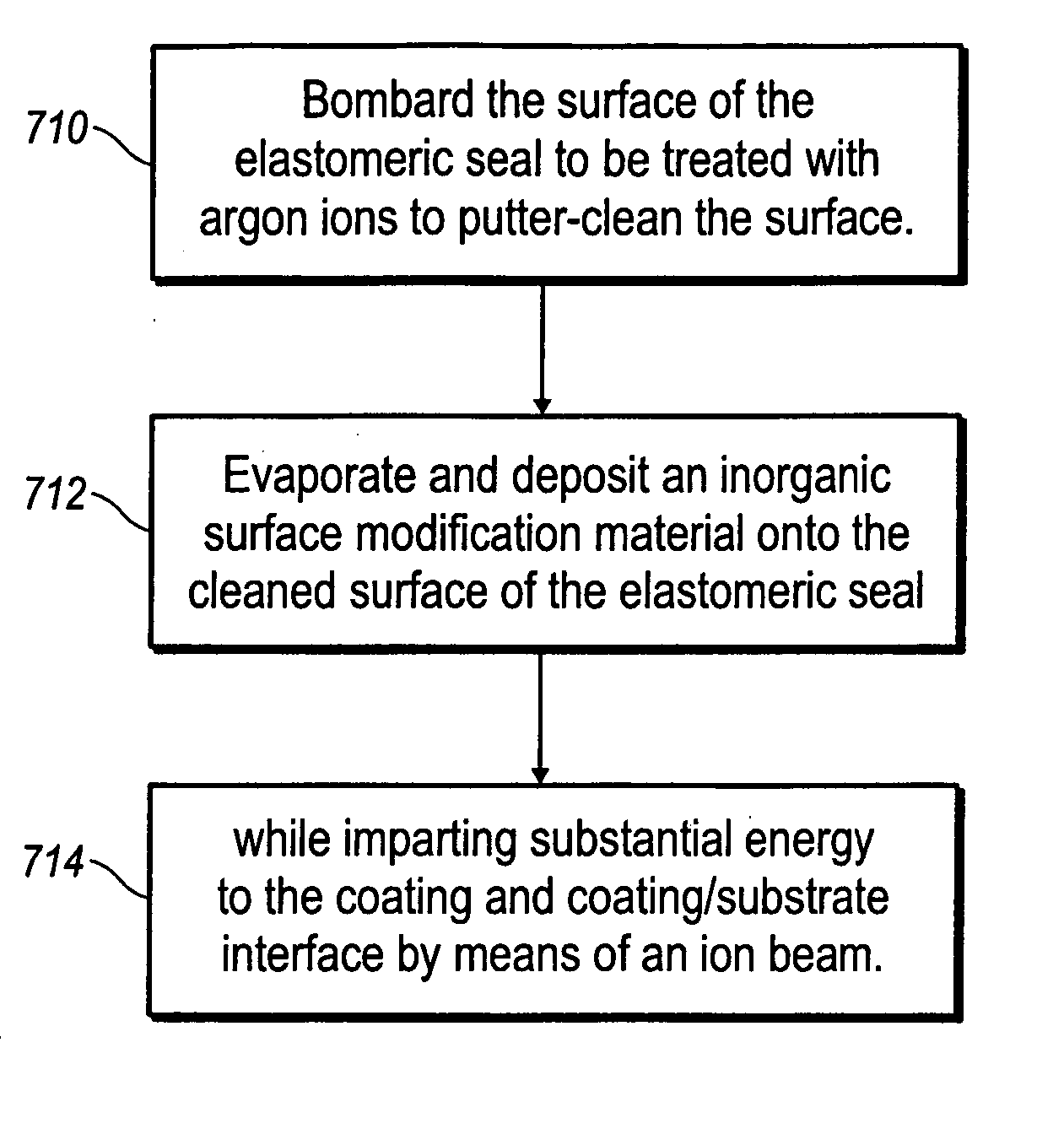
[0041] As illustrated in FIG. 7, in one example embodiment, the elastomeric seals of the present application are initially bombarded with argon ions to putter-clean the surface (step 710). An inorganic surface modification material, such as a metallic or ceramic material, is then evaporated and deposited onto the surface of the elastomeric seals (step 712) while an ion beam imparts substantial energy to the coating and coating / substrate interface (step 714). The inorganic material can be any metal, such as nickel or chromium. The inorganic material can also be any ceramic, including but not limited to chromium nitride or titanium carbide. ...


PUM

PropertyMeasurementUnit
Wear resistanceaaaaaaaaaa
Surface compositionaaaaaaaaaa

Abstract

Elastomeric seals for use in drill bits on which an inorganic surface modification material has been deposited onto the surface of the elastomeric seals. Wear resistance of the seal at the dynamic surface is improved by providing support for the soft seal surface, by means of the inorganic atoms, against a harder surface.

Description

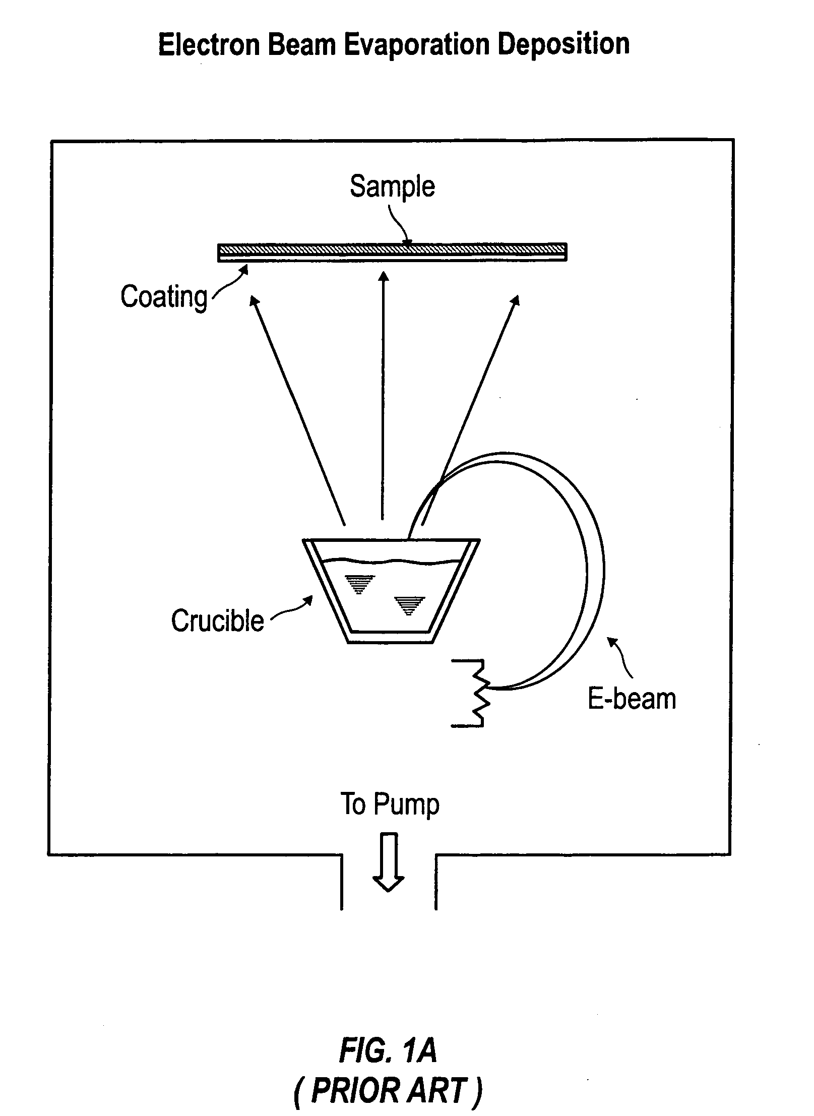
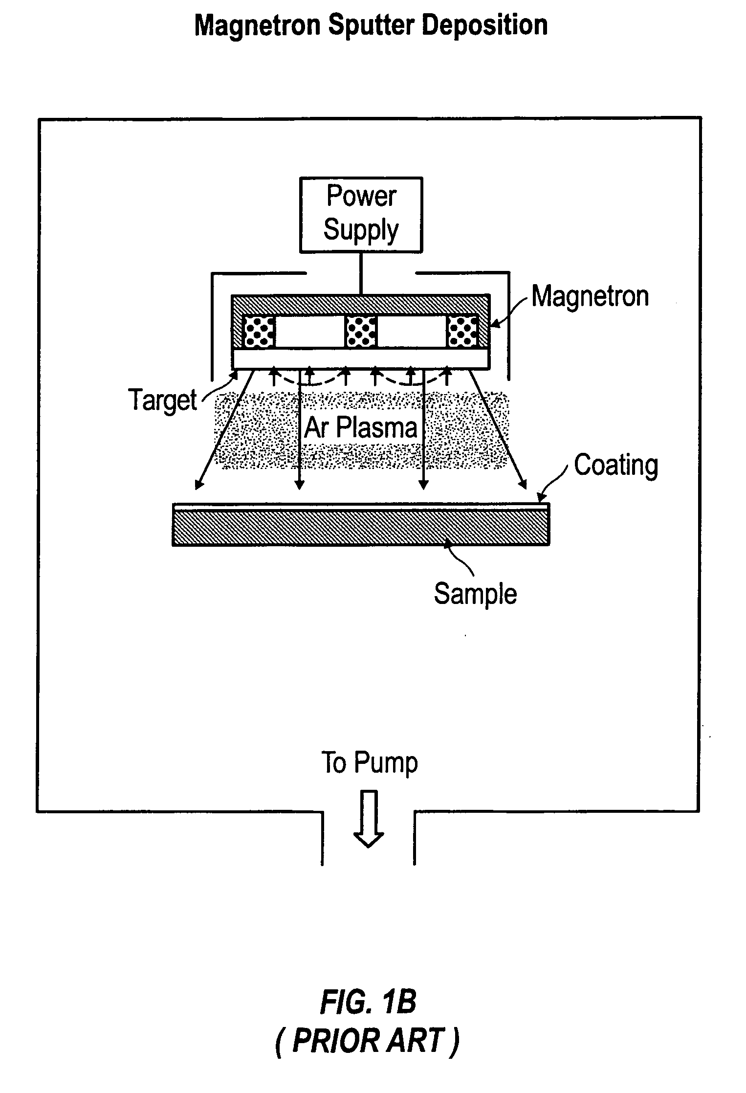
CROSS-REFERENCE TO RELATED APPLICATIONS [0001] This application claims priority from U.S. Provisional Application 60 / 515,055 filed Oct. 28, 2003, which is hereby incorporated by reference.FIELD OF THE INVENTION [0002] The present invention relates to elastomeric seals and, more particularly, to improving the wear resistance of elastomeric seals by using ion-beam assisted deposition to coat elastomeric seals with a hard coating. BACKGROUND AND SUMMARY OF THE INVENTION Background: Physical Vapor Deposition (PVD) [0003] Physical vapor deposition (PVD) processes (often just called thin film processes) are atomistic deposition processes in which material is vaporized from a solid or liquid source in the form of atoms or molecules, transported in the form of a vapor through a vacuum or low pressure gaseous (or plasma) environment to the substrate where it condenses. FIGS. 1A and 1B are general schematics of the PVD process. Typically, PVD processes are used to deposit films with thicknes...

Claims


Application Information

Patent Timeline
IPC IPC(8): C23C14/32F16J
CPCC23C14/022C23C14/20C23C14/221F16J15/108E21B10/25F16J15/102C23C14/30
Inventor SUI, PING C.WEI, RONGHUA
Owner HALLIBURTON ENERGY SERVICES INC
Learn More