Thin-film structure and method for producing the same

a thin film, polarizer technology, applied in the direction of instruments, polarising elements, optical elements, etc., can solve the problems of imposing restrictions on use, large compactness, high luminance, etc., and achieve the effect of low cost and superior characteristics

Inactive Publication Date: 2005-06-09
NIPPON SHEET GLASS CO LTD
View PDF2 Cites 36 Cited by
  • Summary
  • Abstract
  • Description
  • Claims
  • Application Information

AI Technical Summary

Benefits of technology

[0011] The object of the present invention is to overcome these problems and to provide, using only deposition technology, a structure on which plate-shaped bodies are arranged on a substrate surface, thus providing a low-cost polarizer with superior characteristics.

Problems solved by technology

However, this has led to the problem of higher temperatures in the optical system resulting from greater compactness, higher luminance, and the like.
However, with these polarizing plates with organic film, the heat resistant properties are low because of the use of organic material.
However, these polarizing films have narrow working wavelength bands, thus imposing restrictions on use.
However, production of wire-grid polarizers requires high-precision control of wire thickness, distances between wires, and the like.
The equipment needed for these technologies is costly and a large number of steps is needed, thus increasing production costs.
More specifically, it was not possible to obtain the film structure that was disclosed.
This provides inadequate performance for a polarizer and prevents the technology from being used for optical communications, liquid crystal projectors, and the like.

Method used


Image

  • Thin-film structure and method for producing the same
  • Thin-film structure and method for producing the same
  • Thin-film structure and method for producing the same

Examples


first embodiment

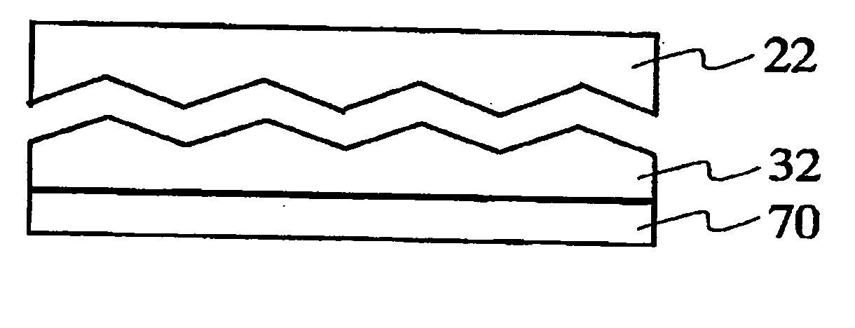
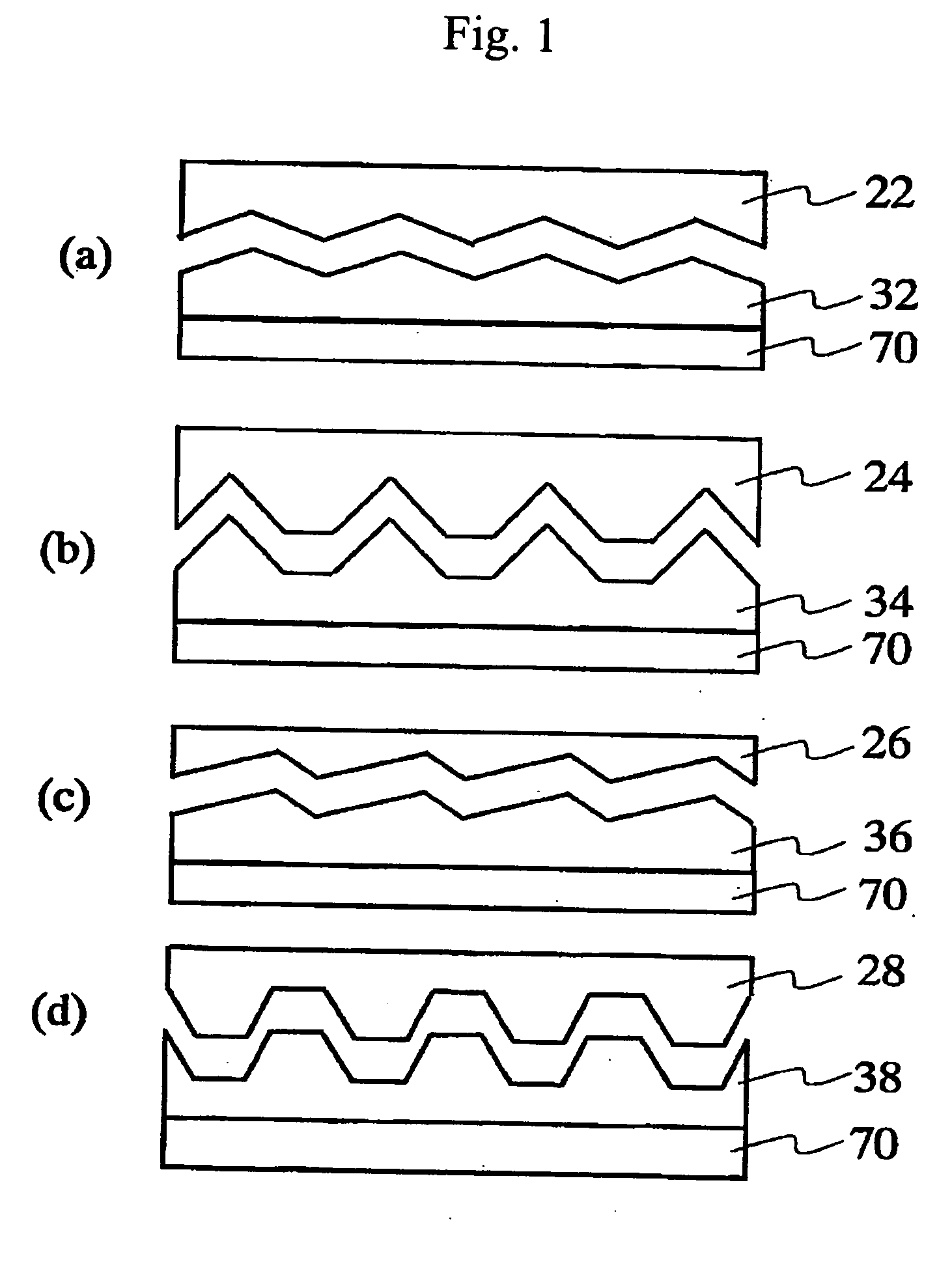
[0063] In this embodiment, line-shaped roughness is formed by molding. FIG. 1 shows various cross-sections of the line-shaped roughness molded in this manner, with the cross-sections being perpendicular to the lines. A spin coater is used to apply a tetraethoxysilane (TEOS)-based sol film on a quartz glass plate. In this embodiment, a mold 22 having the cross-section shape shown in FIG. 1(a) is pressed against this. The structure is then heated and dried and then the mold is released. After these operations, a heat of 600 deg C. is applied so that a rough film 32 having SiO2 as its main component is formed on a glass substrate 70.

[0064] Next, an AgPd alloy target (Pd: 2 wt % added) is attached to a magnetron cathode 1 of the long-distance sputtering device shown in FIG. 10, and an SiO2 target is attached to a magnetron cathode 2. The quartz glass substrate with the rough surface described above is attached at the position of the base 10 shown in FIG. 10. The magnetron cathode 1 is ...

second embodiment

[0071] In this embodiment, sputtering is used to apply an SiO2 film with a thickness of approximately 100 nm to cover the surface of the plate-shaped structure made in the first embodiment. The degree of polarization measured for an incident light wavelength of 632.8 nm was found to be 99.9% or higher, and transmissivity for TM polarized light was found to be 89.7%, these values being adequately high. As Table 1 shows, similar characteristics were found for other wavelengths.

[0072] The sample above was heated for 1 hour at 500 deg C. in the atmosphere. Table 1 shows the results of optical measurements performed after this operation. Optical characteristics roughly identical to the pre-heated state were maintained, and it was found that covering the plate-shaped structure with a dielectric film provided an extremely high degree of heat resistance.

third embodiment

[0073] In this embodiment, the surface of an aluminosilicate glass substrate was abraded using polishing powder (particle diameter: 100 nm) to form line-shaped corrugated structures on the glass surface. The surface corrugated structure structure on the substrate is similar in shape to that of the first embodiment, but the corrugated structure was much more shallow, with the average depth being approximately 15 nm. The average corrugated structure period was 130 nm.

[0074] The following operation was performed in order to accentuate the corrugated structure depth through the formation of a film to cover the surface. Si targets (B dope) were attached to the magnetron cathode 1 and the magnetron cathode 2 in the long-distance sputtering device shown in FIG. 10. A glass substrate having the corrugated structured structure described above was then attached to the position of the base 10 shown in FIG. 10. The magnetron cathode 1 was inclined 80 deg relative to the normal direction of the...


PUM

PropertyMeasurementUnit
widthaaaaaaaaaa
heightaaaaaaaaaa
heightaaaaaaaaaa

Abstract

A thin-film structure includes plate-shaped metals or plate-shaped structures in which a plate-shaped metal and a plate-shaped dielectric are in contact. The plate-shaped metal or structures are formed on a transparent base having a surface with line-shaped corrugated structures. The plate-shaped metals or structures are perpendicular to or oblique to the surface of the base. The thin-film structure has characteristics suitable for polarizers used in liquid crystal projectors and the like.

Description

INCORPORATION BY REFERENCE [0001] The present application claims priority under 35 U.S.C. §119 of Japanese Patent Application No. 2003-400284 filed on Nov. 28, 2003. The content of the application is incorporated herein by reference in its entirety. BACKGROUND OF THE INVENTION [0002] The present invention relates to a polarizer used in liquid crystal display devices, optical recording devices, optical sensors, and the like. More specifically, the present invention relates to a thin-film structure having polarization characteristics needed for polarizers and a method for making the same. [0003] A polarizer is an optical element that extracts polarized light having a specific orientation from light containing multiple polarizations. Various types of polarizers have been proposed and implemented in practice. Examples include: polarized glass, in which column-shaped silver particles having high aspect ratios is dispersed in glass; polarizers in which island-shaped metal layers are alter...

Claims


Application Information

Patent Timeline
Patent Type & Authority Applications(United States)
IPC IPC(8): C03C17/06G02B5/30G02F1/1335
CPCC03C17/3607C03C17/3647C03C2217/77G02F2001/133548C03C2218/154G02B5/3058G02F1/133528C03C2218/113G02F1/133548
Inventor KUNISADA, TERUFUSAKUSAKA, SATORUNAKAMA, KENICHI
Owner NIPPON SHEET GLASS CO LTD
Why Eureka
Try Eureka