Removable labels, coupons and the like

a technology of labels and coupons, applied in the direction of identification means, seals, instruments, etc., can solve the problems of limiting the use of polymeric films as substrates, affecting the appearance, and affecting the effect of treatment effect, so as to increase or decrease the exposure time of treatment, increase or decrease the distance

Inactive Publication Date: 2005-06-09
POLYMERIC CONVERTING
View PDF15 Cites 31 Cited by
  • Summary
  • Abstract
  • Description
  • Claims
  • Application Information

AI Technical Summary

Benefits of technology

[0106] the surface modification that is achieved by the surface treatment is based on the use of a predetermined power level that is varied by increasing or decreasing the power of the treatment, by increasing or decreasing the exposure time of the treatment, or by increasing or decreasing the distance between the treatment source and the surface to which said treatment is applied.

Problems solved by technology

This technique limits the use of polymeric films as substrates because perforations can be difficult to tear and will tear randomly in direction.
The non adhesive coated area tends to pucker or wrinkle as the article it is affixed to is flexed, bent or undergoes changes in environmental conditions which is aesthetically unacceptable.
These techniques while difficult to manufacture, have been found to be necessary commercially to begin separation of the sheets without excessive picking at the edge.
It is not acceptable to have to frustratingly pick at the edge while possibly damaging the label when the bond of the sheets is as strong as needed to prevent pre-separation through manufacturing, handling and labeling.
It is not universally acceptable to have consumers remove the sticky edged label to access the back portion to remove it, especially if it contains warning and hazard information.
Many of the labels will be damaged or not reapplied leaving hazardous unmarked containers.
Even though there is a release point at the release film interface with the release coating, this product is not universally acceptable because of the complex manufacturing requirements and the fact that the release force must be fairly tight to prevent pre-release in handling and processing which causes the user to pick at the edge with a fingernail in hopes of starting the release film to remove without damaging the face sheet.
This is a difficult, high waste and time consuming process versus registering front to back on one sheet which is commonly done on conventional printing equipment which can not be employed in this case because the release coating does not allow for transfer to it.
Additionally, while there is a release point at the adhesive interface with the release coating, this product is not universally acceptable because, as in Eagon, the release force must be fairly tight to prevent pre-release in handling and processing which causes the user to pick at the edge with a fingernail in hopes of starting the release film to remove without damaging the face sheet.
In addition, ease of separation is difficult because the controlled interfacial bond must be tight enough to facilitate handling, processing and application which again means the end user must pick at the edge because it is the same controlled release across the entire coextruded film.
The mechanism of bonding thermal layers in this case is different from the other prior art of release layers, controlled interfacial coextruded bonds, dry splittable adhesives and the like but the same problem of ease of lift still exists.
This product is not universally accepted because of the random splittable nature of the adhesive leaves a residue on the back of the removable piece that aesthetically can negatively impact graphics below it.
While this system can work successfully, special pattern non adhesive areas on the face material are needed to laminate to the breakaway layer that adds significant cost and the converter must die cut in register to the non adhesive area complicating processing.

Method used


Image

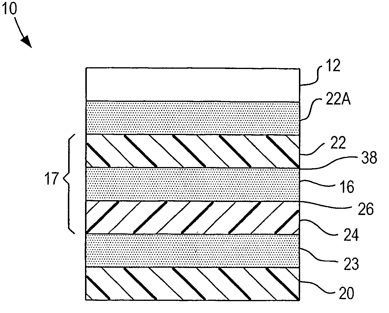
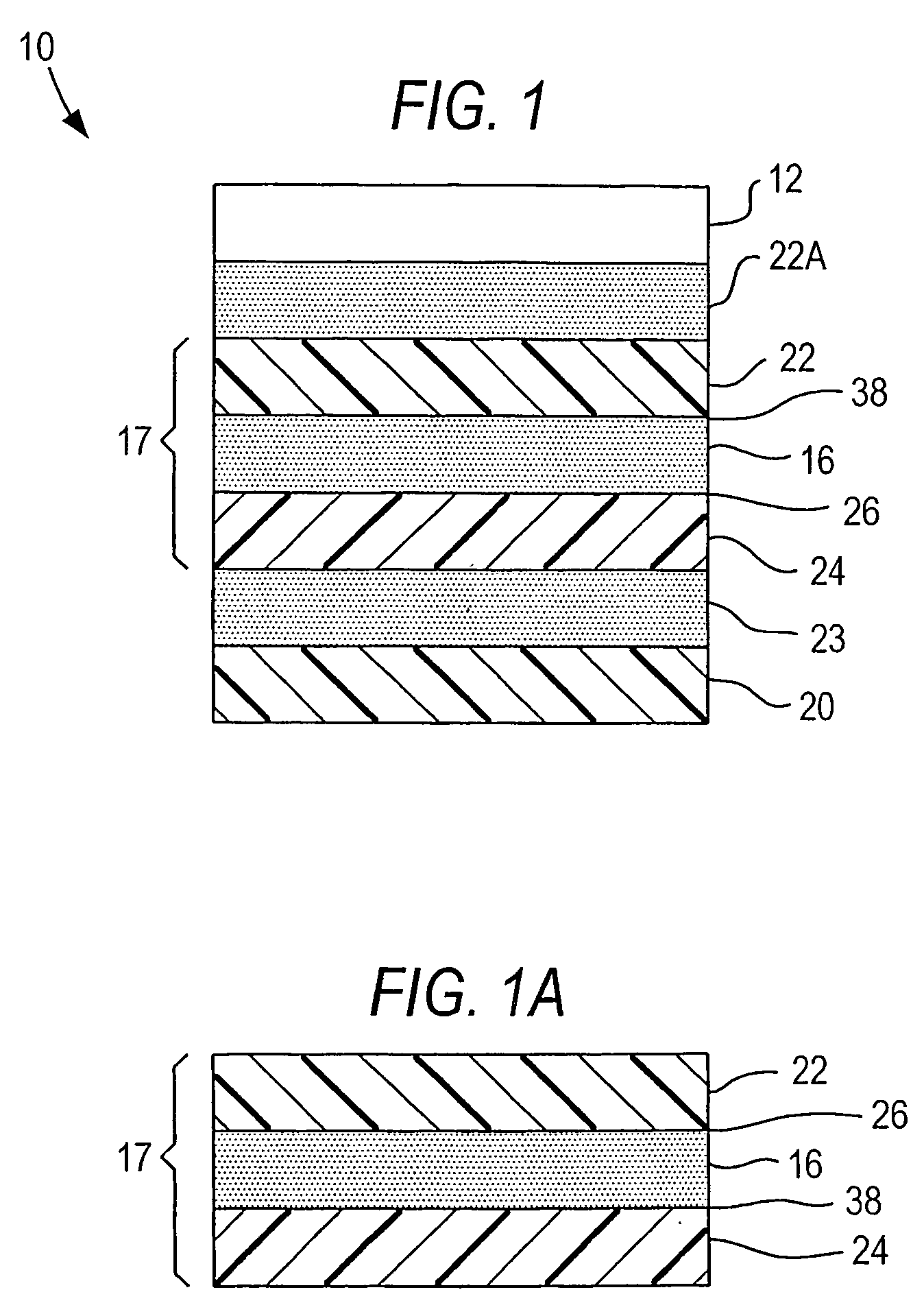
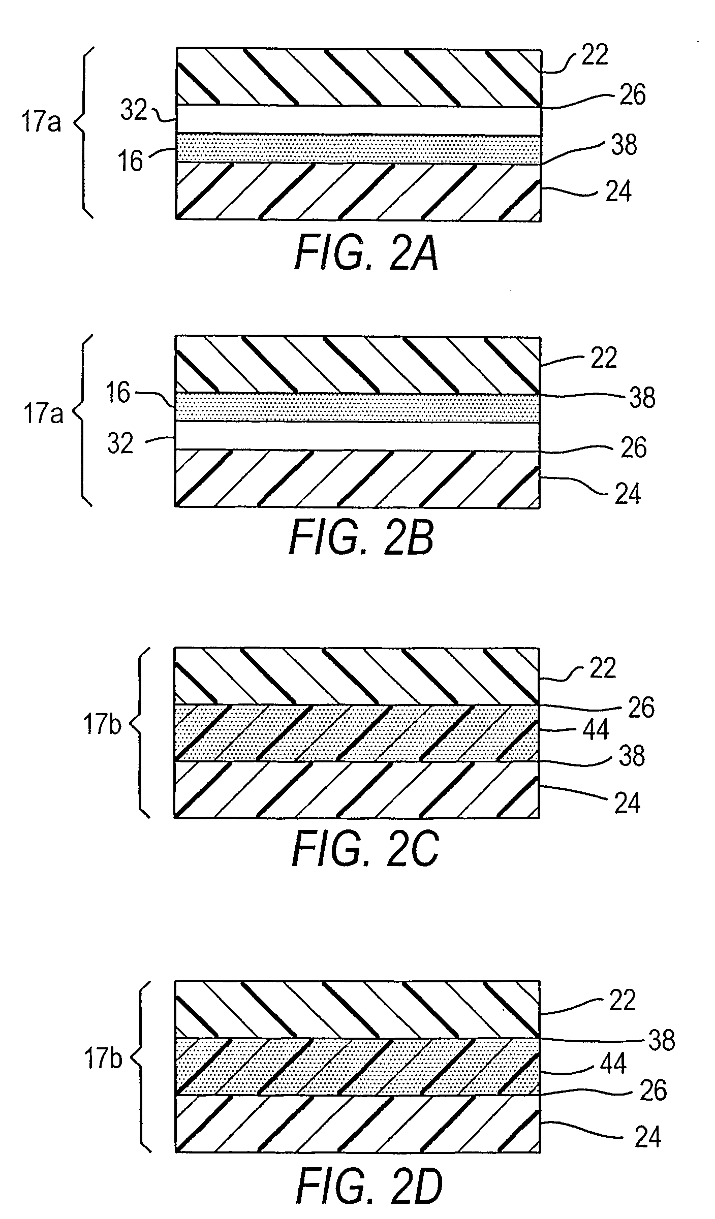
  • Removable labels, coupons and the like
  • Removable labels, coupons and the like
  • Removable labels, coupons and the like

Examples


example 1

[0128] A convential web of non-surface-treated 144 gauge oriented PET polyester (1.44 mil) (available from Advanced Web Products, 529 Fifth Ave., NY, USA) was corona discharge treated at 100 ft / min. using a power supply (model No. AB6628) available from Pillar Technologies, Inc., Heartland, Wis., USA, and a modified corona treater (AB1977) which was designed to operate with a rotary electrode according to FIG. 4 using a pattern of lands and valleys as in FIG. 3 on a 45 degree angle across the running direction of the width of the material to form a pattered treated web. The width of the treated area was {fraction (3 / 16)} inches and the non-treated area was {fraction (3 / 16)} inches.

[0129] A 100% surface treated web of 200 gauge oriented PET polyester was prepared using a power output of 0.4 KW and corona discharge apparatus adapted to treat the whole surface. This treated web was gravure coated with a modified carboxylated acrylic latex prepared as follows: 80 parts Hystrex V43 (acr...

example 2

[0133] Non-surface-treated 65 gauge oriented PET polyester (0.65 mil) was corona discharge treated in a sine wave pattern continuously across a web using the modified corona treater described in Example 1. Using the power outputs set forth in Table II the amplitude of the sine wave was {fraction (1 / 4)} inch and the thickness of the electrode providing the treatment was {fraction (3 / 32)} inch the frequency of the sine wave one-half inch running in the machine direction with a phase difference of one-half inch across the web.

[0134] A coating of a modified polyurethane available from Adhesion Systems, Patterson, N.J., AS37637 (19-21% solids; viscosity 100-500 cps) was applied at a coat weight of 0.8 grams dry / 1000 sq. in. immediately following treatment. The resulting coated web is laminated with laminating adhesive PD384-30 Adhesion Systems Inc. (38-40% solids; 20-200 CPS at 60 psi and 140° F.) mixed with 1% of a 100% solid polyfunctional aziridine cross-linker (AS316 Adhesion System...


PUM

PropertyMeasurementUnit
thickaaaaaaaaaa
surface tension testaaaaaaaaaa
peel angleaaaaaaaaaa

Abstract

An article of manufacture of removable segments, labels, coupons, and the like, as for identification, rewards and inventory control, which includes a support substrate film (17) structure having one or more selectively-pattern-treated (16) laminae for adhesively, but cleanly releasably, securing the segments, coupons and labels to the support structure (17).

Description

FIELD OF THE INVENTION [0001] This invention relates to removable labels and coupons, as for purchase rebate awards, expanded information labels, game pieces, coupons and the like which include a portion to be adapted to identify an article and a portion to be peeled off. More particularly the removable portion comprises a sub-laminate with a selectively-patterned surface treated interface providing differential release properties, which, in turn, is adhesively secured to a support structure, such as a release paper, an article to be identified, or a container, and the like. BACKGROUND OF THE INVENTION [0002] Dronzek, Jr., in co-pending U.S. Patent Application Serial No., filed concurrently herewith under Attorney's Docket No. 181-037, describes card intermediates such as a business form having an integral and removable card portion are unexpectedly improved if some of the films used as laminae with the form are patterned in a judicious way during surface treatment. It has been foun...

Claims


Application Information

Patent Timeline
Patent Type & Authority Applications(United States)
IPC IPC(8): B32B7/06B32B7/12B32B27/06B32B37/00B32B37/30G09F3/02G09F3/10
CPCB32B7/06Y10T428/1486B32B27/06B32B37/0076B32B38/0008B32B2310/0445B32B2519/00G09F3/02G09F3/10Y10T428/14Y10T428/1481Y10T428/149Y10T428/15Y10T428/1495Y10T428/1471B32B7/12
Inventor DRONZEK, PETER J JR.GERVAIS, JOSEPH R.
Owner POLYMERIC CONVERTING
Why Eureka
Try Eureka