Organic element for electroluminescent devices

a technology of electroluminescent devices and organic elements, applied in the direction of luminescnet screens, discharge tubes, natural mineral layered products, etc., can solve the problems of large loss of efficiency, performance limitations, and a large barrier to many desirable applications

Inactive Publication Date: 2005-06-09
EASTMAN KODAK CO
View PDF4 Cites 9 Cited by
  • Summary
  • Abstract
  • Description
  • Claims
  • Application Information

AI Technical Summary

Benefits of technology

[0011] The invention provides an electroluminescent device comprising a cathode, an anode, and located therebetween a light emitting layer (LEL) containing (1) a host material that comprises a N,N,N′,N′-tetra-aromatic benzidine group substituted in at least one position ortho to the biphenyl linkage between the phenyl groups of the benzidine nu

Problems solved by technology

While organic electroluminescent (EL) devices have been known for over two decades, their performance limitations have represented a barrier to many desirable applications.
However, it is generally

Method used


Image

  • Organic element for electroluminescent devices
  • Organic element for electroluminescent devices
  • Organic element for electroluminescent devices

Examples


synthetic example 1

Preparation of Inv-11

[0146]4,′4-Diaminooctafluorobiphenyl (Aldrich, 2.0 g, 6.1 mmol), 4-bromobiphenyl (Aldrich, 7.5 g, 32.2 mmol) palladium diacetate (150 mg, 0.7 mmol), tri-t-butylphosphine (0.6 mL), sodium t-butoxide (2.8 g, 29.2 mmol), and xylene (90 mL) were combined in a 250 mL-flask with magnetic stirring and condensor. The mixture was heated at 125° C. under a nitrogen atmosphere for 6 h. The heat was removed and after, cooling to room temperature, a solid was collected by filtration. This material was dissolved in methylene chloride and filtered. The filtrate was evaporated. The solid obtained was slurried with ligroin and then collected. This material was sublimed twice at 380° C. under vacuum (0.6 Torr) with a stream of nitrogen gas to afford Inv-11, mass spectrum m / e: 937.

example 1

DEVICE EXAMPLE 1

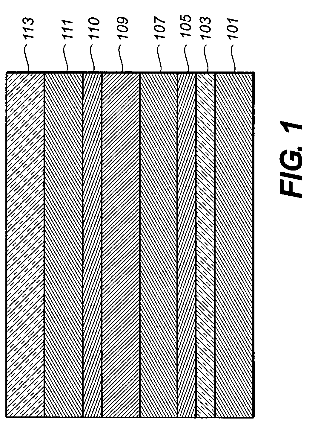
[0147] An EL device (Sample 1) satisfying the requirements of the invention was constructed in the following manner: [0148] 1. A glass substrate coated with an 85 nm layer of indium-tin oxide (ITO) as the anode was sequentially ultrasonicated in a commercial detergent, rinsed in deionized water, degreased in toluene vapor and exposed to oxygen plasma for about 1 min. [0149] 2. Over the ITO was deposited a 1 nm fluorocarbon (CFx) hole-injecting layer (HIL) by plasma-assisted deposition of CHF3. [0150] 3. A hole-transporting layer (HTL)of N,N′-di-1-naphthyl-N,N′-diphenyl-4,4′-diaminobiphenyl (NPB) having a thickness of 75 nm was then evaporated from a tantalum boat. [0151] 4. A 35 nm light-emitting layer (LEL) of Inv-11 and a green phosphorescent dopant, fac-tris(2-phenylpyridinato-N,C2′)iridium(III), (Ir(ppy)3), 3% wt %) were then deposited onto the hole-transporting layer. These materials were also evaporated from tantalum boats. [0152] 5. A hole-blocking layer of bi...

example 2

DEVICE EXAMPLE 2

[0158] An EL device (Sample 6) satisfying the requirements of the invention was constructed in the same manner as Sample 1, except a red phosphorescent dopant (RPD-1) was used in place of Ir(ppy)3.:

[0159] Samples 7, 8 and 9 were fabricated in an identical manner to Sample 6 except emitter RPD-1 was used at the level indicated in the table. Sample 10 was fabricated in an identical manner to Sample 6 except compound RPD-1 was not included. The cells thus formed were tested for luminance, efficiency and color CIE coordinates at an operating current of 20 mA / cm2 and the ported in Table 2.

TABLE 2RPD-1Evaluation Results for EL devices.RedDopantLevelLuminanceEfficiencySample(%)(cd / m2)(W / A)CIExCIEyType633170.0400.6530.316Invention765070.0650.6770.318Invention895960.0760.6760.318Invention9126760.0870.6770.319Invention100740.0040.2460.360Comparison

[0160] As can be seen from Table 2, all tested EL devices incorporating the invention compound as a host material for the red ph...


PUM

PropertyMeasurementUnit
Angleaaaaaaaaaa
Angleaaaaaaaaaa
Angleaaaaaaaaaa

Abstract

Disclosed is an electroluminescent device comprising a cathode, an anode, and located therebetween a light emitting layer (LEL) containing (1) a host material that comprises a N,N,N′,N′-tetra-aromatic benzidine group substituted in at least one position ortho to the biphenyl linkage between the phenyl groups of the benzidine nucleus and (2) a phosphorescent light emitting material, wherein the triplet state energy of the benzidine nucleus is higher than the triplet state energy of the phosphorescent emitting material.

Description

FIELD OF THE INVENTION [0001] This invention relates to an electroluminescent device comprising a cathode, an anode, and located therebetween a light emitting layer (LEL) containing (1) a host material that comprises a N,N,N′,N′-tetra-aromatic benzidine group substituted in at least one position ortho to the biphenyl linkage between the phenyl groups of the benzidine nucleus and (2) a phosphorescent light emitting material, wherein the triplet state energy of the benzidine nucleus is higher than the triplet state energy of the phosphorescent emitting material. BACKGROUND OF THE INVENTION [0002] While organic electroluminescent (EL) devices have been known for over two decades, their performance limitations have represented a barrier to many desirable applications. In simplest form, an organic EL device is comprised of an anode for hole injection, a cathode for electron injection, and an organic medium sandwiched between these electrodes to support charge recombination that yields em...

Claims


Application Information

Patent Timeline
IPC IPC(8): C07C209/00C07C211/00C09K11/06H01L51/00H01L51/50H05B33/14
CPCC09K11/06H05B33/14C09K2211/1014C09K2211/1029C09K2211/1055C09K2211/1085C09K2211/1092C09K2211/1408C09K2211/185H01L51/0052H01L51/0059H01L51/0062H01L51/0081H01L51/0085H01L51/5016H01L2251/308C09K2211/1011H10K85/649H10K85/615H10K85/631H10K85/324H10K85/342H10K50/11H10K2101/10H10K2102/103
Inventor GIESEN, DAVID J.PARTON, RICHARD L.TANG, CHING W.
Owner EASTMAN KODAK CO
Why Eureka
Try Eureka