Fuel cell system and related method

a fuel cell and system technology, applied in the field of fuel cell systems, can solve the problems of degrading the performance of the combustion chamber, and achieve the effects of reducing the temperature of the outlet gas, and lowering the temperature of the combustion chamber

Inactive Publication Date: 2005-06-09
NISSAN MOTOR CO LTD
View PDF2 Cites 41 Cited by
  • Summary
  • Abstract
  • Description
  • Claims
  • Application Information

AI Technical Summary

Benefits of technology

[0009] However, since the above-described technology has a structure wherein if a detected value of a combustion chamber outlet temperature exceeds a temperature upper limit value, an air flow rate is increased to lower the temperature of the combustion chamber. Therefore, when intermittent and short-term combustion is performed in the combustion chamber, the temperature rise in the outlet gas temperature decreases due to a thermal capacity present in the combustion chamber. Thus, since the combustion temperature exceeding the temperature upper limit value is unable to be detected, as a result performance of the combustion chamber is degraded.
[0010] To address such an issue, an aspect of the present invention is a fuel cell system which comprises a fuel gas supply unit supplying fuel gas, an oxidant gas supply unit supplying oxidant gas, a fuel cell stack generating electric power using the fuel gas and the oxidant gas, an anode off-gas recirculation unit recirculating anode off-gas, discharged from an anode of the fuel cell stack, to the anode, a purging unit temporarily discharging the anode off-gas from the anode off-gas recirculation unit to an outside thereof, a combustor combusting at least the anode off-gas, discharged from the purging unit, and the oxidant gas or cathode off-gas discharged from a cathode of the fuel cell stack, and a system controller operative to perform system control such that when permitting the purging unit to discharge the anode off-gas to the combustor, a combustion temperature of the combustor does not exceed a given temperature.
[0011] According to another aspect of the present invention, there is provided a method of controlling a fuel cell system, which method comprises preparing a fuel gas supply unit supplying fuel gas, an oxidant gas supply unit supplying oxidant gas, a fuel cell stack generating electric power using the fuel gas and the oxidant gas, a combustor combusting at least anode off-gas, discharged from an anode off-gas and the oxidant gas or cathode off-gas, discharged from a cathode of the fuel cell stack, discharging anode off-gas from the anode of the fuel cell stack, recirculating the anode off-gas, discharged from an air supply unit or the anode of the fuel cell stack, to the anode, combusting at least the anode off-gas, discharged from the anode of the fuel cell stack, and the oxidant gas or cathode off-gas discharged from the cathode of the fuel cell stack, and executing system control such that when permitting the anode off-gas to be discharged to the combustor, a combustion temperature of the combustor does not exceed a given temperature.

Problems solved by technology

Thus, since the combustion temperature exceeding the temperature upper limit value is unable to be detected, as a result performance of the combustion chamber is degraded.

Method used


Image

  • Fuel cell system and related method
  • Fuel cell system and related method
  • Fuel cell system and related method

Examples


first embodiment

[0036] Referring to FIGS. 1 to 3, a first embodiment of a fuel cell system according to the present invention is described in detail below.

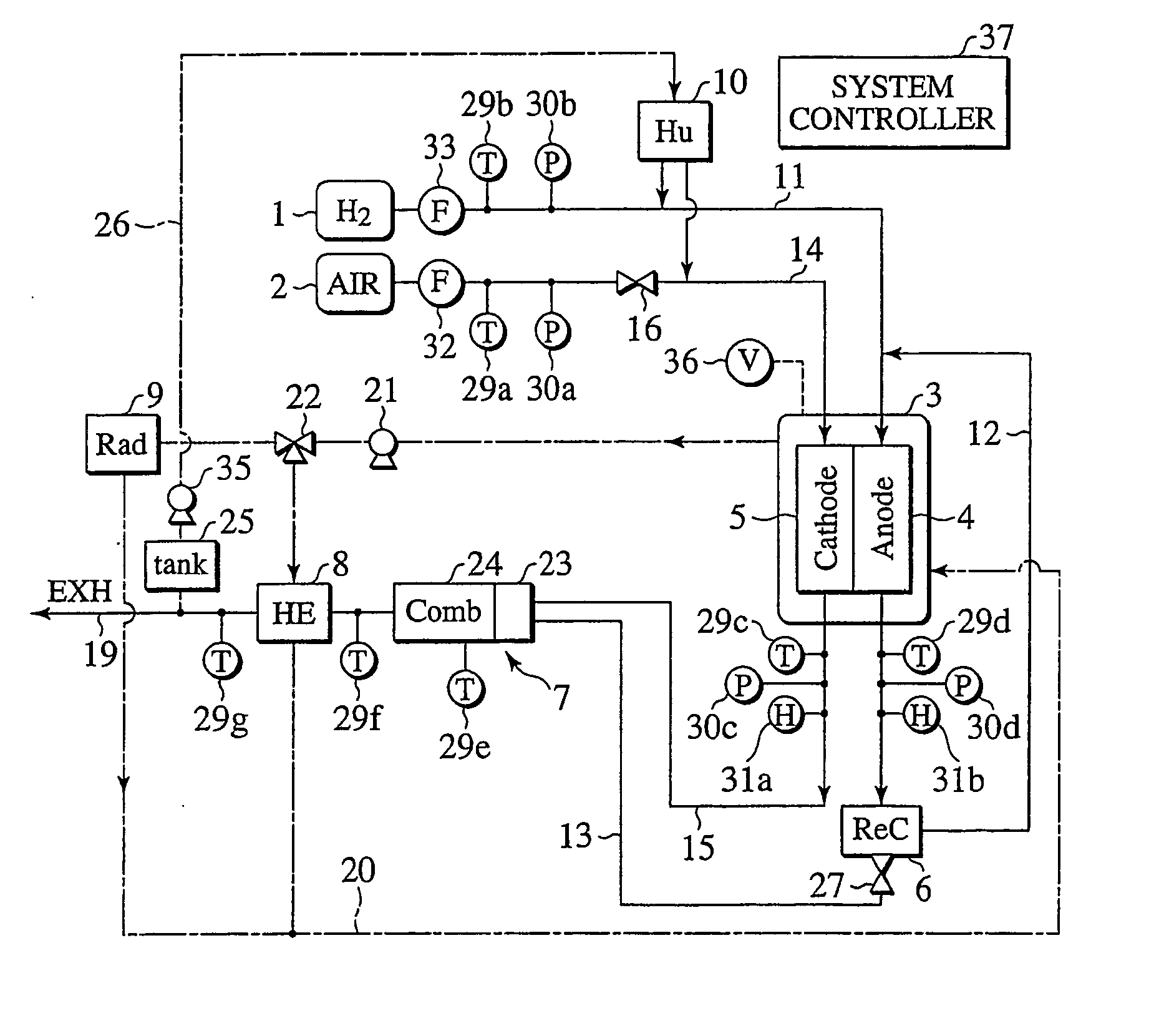
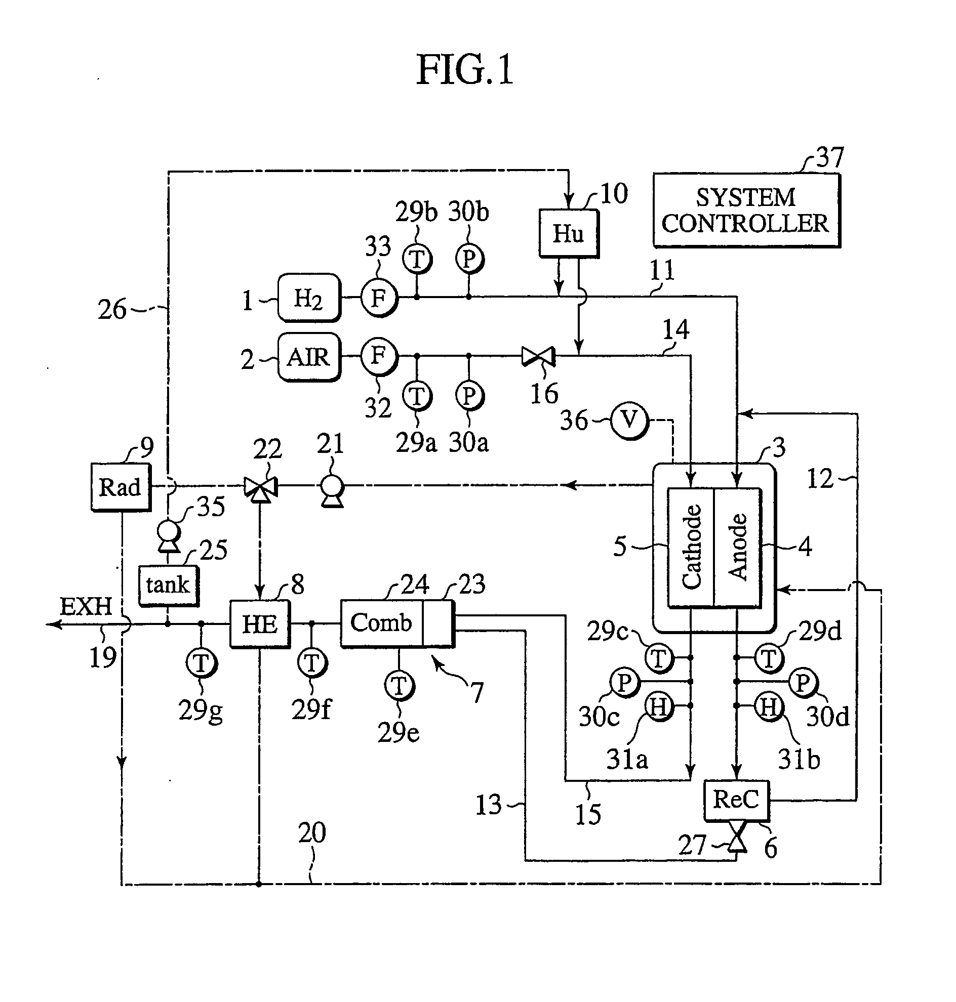
[0037]FIG. 1 is a system structural view illustrating a structure of the first embodiment. In the figure, the fuel cell system is comprised of a hydrogen supply unit (fuel gas supply unit) 1 that supplies hydrogen as fuel gas; an air supply unit (oxidant gas supply unit) 2 that supplies air as oxidant gas; a fuel cell stack 3 that includes electrodes, such as an anode 4 and a cathode 5, which are supplied with hydrogen and air, respectively, to generate electric power; an anode off-gas recirculation unit 6 that allows anode off-gas to be recirculated to an upstream side of the anode 4 via an anode off-gas recirculation conduit 12; a coolant heat exchanger 8 that heats coolant with combustion exhaust gas of a combustor 7 during start-up; a coolant cooling unit 9; a humidifier 10 that allows hydrogen and air to be humidified, an air flow control v...

second embodiment

[0089] Next, referring to FIGS. 4 to 6, detailed description is made of a second embodiment of a fuel cell system according to the present invention.

[0090]FIG. 4 is a system structural view illustrating a structure of the second embodiment. In the second embodiment, the fuel cell system is constructed such that an air flow control valve 17 and an air supply conduit 18 are additionally located between the air supply unit 2 and the combustor 7 to enable a portion of air supplied from the air supply unit 2 to be branched off and directly supplied to the combustor 7. The second embodiment is similar in other structure to that of the first embodiment shown in FIG. 1 and, so, like component parts bear the same reference numerals as those of the first embodiment for omitting duplicated description.

[0091] With such a structure set forth above, the presently filed embodiment is enabled to directly supply air from the air supply unit 2 to the combustor 7 through the air flow control valve 1...

third embodiment

[0108] Next, referring to FIGS. 7 to 9, a third embodiment of a fuel cell system according to the present invention is described in detail.

[0109]FIG. 7 is a system structural view illustrating a structure of the third embodiment. The third embodiment contemplates to further include, in addition to the component elements of the first embodiment shown in FIG. 1, an auxiliary air supply unit 28 that supplies auxiliary air specific for the combustor 7, an auxiliary air flow meter 38 that measures the flow rate of auxiliary air, and a temperature detector 29h that detects the temperature of auxiliary air to be supplied from the auxiliary air supply unit 28. The third embodiment is similar in other structure to that of the first embodiment shown in FIG. 1 and, so, like component parts bear the same reference numerals as those of the first embodiment for omitting duplicated description.

[0110] In contrast to the first and second embodiments, since the third embodiment is configured to all...


PUM

PropertyMeasurementUnit
electric poweraaaaaaaaaa
combustion temperatureaaaaaaaaaa
temperatureaaaaaaaaaa

Abstract

A fuel cell system and related method are disclosed having a system controller 37 that executes enthalpy calculation based on status signals, related to anode off-gas and cathode off-gas, detected by a temperature detector 29, a pressure detector 30 and a humidity detector 31 for thereby predicting a combustion temperature of a combustor 7 during purging. In the presence of a predicted combustion temperature exceeding an upper limit, cathode off-gas is increased in volume to limit a combustion temperature of the combustor 7 to a value below the upper limit value.

Description

TECHNICAL FIELD [0001] This invention relates to fuel cell systems and, more particularly, to a fuel cell system, that provides improved temperature control of a combustor for combusting anode off-gas, and a related method. BACKGROUND ART [0002] In a fuel sell system, fuel gas such as hydrogen and oxidant gas containing oxygen electrochemically react each other via electrolyte to take out an electric energy from electrodes disposed on both sides of an electrolyte. Especially, a solid polymer fuel cell employing a solid electrolyte attracts public attention as an electric power supply for an electric vehicle because of a low operating temperature and ease of handling. A fuel cell powered vehicle is an ultimate clean vehicle with only water remaining as emission matter. This vehicle install a hydrogen absorbing device, such as a high pressure hydrogen tank, a liquid hydrogen tank, and a hydrogen absorbing amorphous alloy tank. Hydrogen supplied from the hydrogen absorbing device and a...

Claims


Application Information

Patent Timeline
Patent Type & Authority Applications(United States)
IPC IPC(8): H01M8/10H01M8/04H01M8/06
CPCH01M8/04007H01M8/04022H01M8/04097Y02E60/50H01M8/0606H01M8/0662H01M8/04231H01M8/04268H01M8/04029H01M8/04
Inventor MATOBA, TADASHIOBATA, TAKEAKI
Owner NISSAN MOTOR CO LTD
Why Eureka
Try Eureka