
Ultrasonic transducer probe

Inactive Publication Date: 2005-06-16
BIOSCAN
View PDF24 Cites 88 Cited by
  • Summary
  • Abstract
  • Description
  • Claims
  • Application Information

AI Technical Summary

Benefits of technology

[0012] In an exemplary embodiment of the invention, different absorbing regions are provided for different wavelengths. Optionally, one terminating region is provided to absorb all relevant wavelengths. Optionally, there is a spatial overlap between absorbing regions for different frequencies, for example a 0.1 mm region that absorbs a first wavelength includes a 0.05 mm sub-region that absorbs a second wavelength in addition to the first wavelength. Such overlap potentially increases the design flexibility in controlling the acoustic transmission envelope, direction and / or frequency.
[0014] In an exemplary embodiment of the invention, the waveguide is used to guide the radiating energy to ensure that most or all of the energy passes through the (one or more) absorbing region. Thus, beam expansion and diffraction problems can be avoided.
[0017] In an exemplary embodiment of the invention, multiple absorption regions are placed along the wave-guide. The type, dimensions and relative positions of these regions may be used to determine the characteristics of the generated ultrasound. Suitable arrangements can optionally determine the directionality, spectral contents, waveform, and the intensity of the ultrasonic radiation. A potential benefit of multiple or extended regions is better heat dissipation, possibly allowing higher ultrasonic peak-power to be effectively used.
[0019] In an exemplary embodiment of the invention, a plurality of absorbing regions are used to generate a strong acoustic wave while maintaining a low average acoustic radiation power, which radiation power is desirably below a break-down point of the absorbing target. The plurality of absorbing regions allows the target to accumulate a larger overall acoustic power while maintaining the peak power level at each region below a specified threshold.

Problems solved by technology

However, transmission of electrical power and / or signals through such thin catheters challenges the design and constrains the ability to reduce the cross-section of the devices.
The resulting thermal stress generates an acoustic disturbance propagating away from the heated region.
Thus, this design necessarily requires a significantly larger diameter than a catheter utilizing a single fiber.
In addition, the power of the ultrasound generated by this patent is apparently constrained by several fundamental loss processes: (a) most of the powering laser light is apparently lost by reflection from the metallic target, some into surrounding tissue (with an added potential health hazard), and (b) most of the resulting ultrasound is apparently dissipated within the construction of the catheter.
The later effect reduces the effectiveness of the system both in the introduction of uncontrolled ultrasonic signals that introduce large background interference that severely compromises the performance of the device as well as in a significant reduction in the available power.
In addition, unwanted power is apparently also absorbed by the surrounding tissue.

Method used


Image

  • Ultrasonic transducer probe
  • Ultrasonic transducer probe
  • Ultrasonic transducer probe

Examples


Embodiment Construction

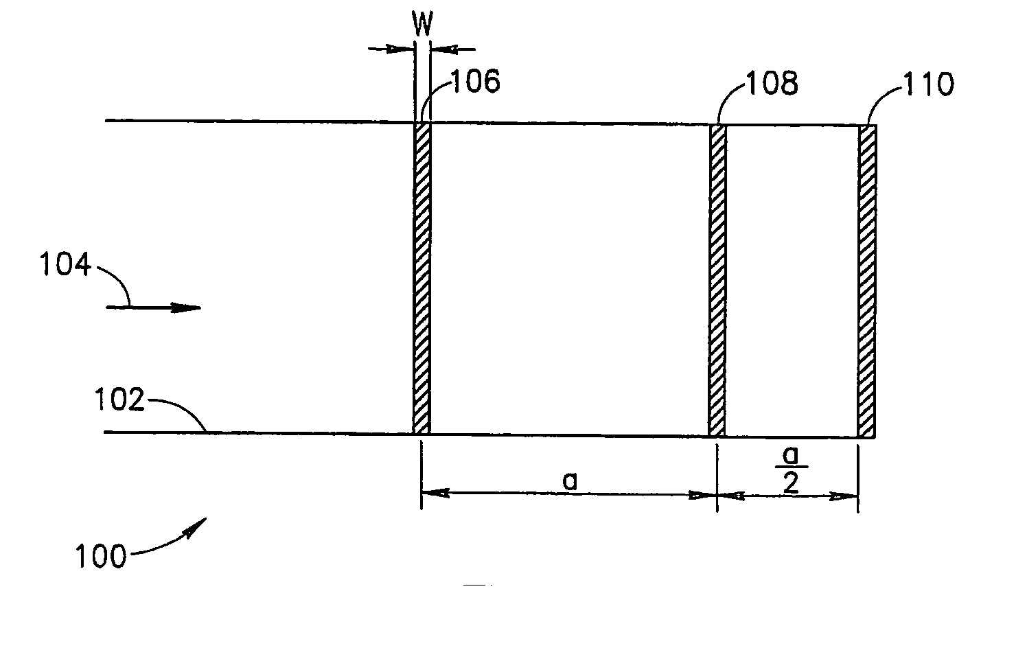
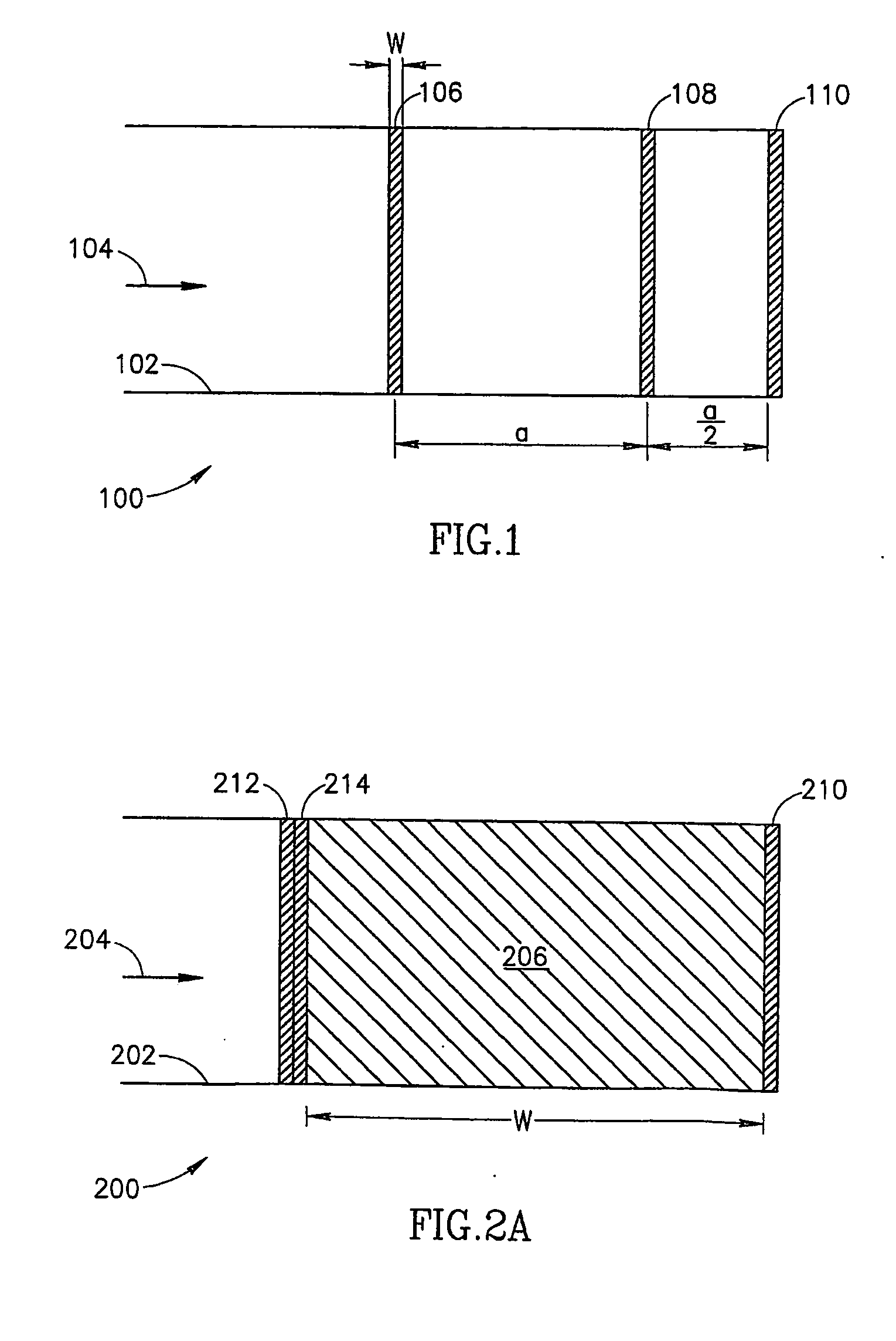
[0103]FIG. 1 is a schematic illustration of an ultrasound generating optical fiber 100, in accordance with an exemplary embodiment of the invention. Fiber 100 includes a body 102 through which a pulse (or train of pulses, or another waveform such as a saw-tooth or Gaussian form) of electro-magnetic radiation 104 (indicated by an arrow), for example infra-red, ultraviolet or visible light, propagates. At least some of the illumination is absorbed by an absorber 106, thereby heating it and causing it to expand abruptly and emit an ultrasonic wave. This wave is typically a multi-spectral wave. As explained in the following, however, the spectrum and / or direction of the wave may be manipulated.

[0104] Potential advantages of using guided-volumetric absorption are: [0105] (a) The generating radiation can be guided through the absorption process and is thereby confined laterally. Lateral spreading of the generating wave through the absorption process as would occur in unguided situations ...


PUM


Abstract

An acoustic generator, comprising: a source of electro-magnetic radiation; a waveguide coupled to said source; and at least one absorbing region defined in said waveguide, said region being selectively absorbing for portions of said radiation meeting at least one certain criterion and having significantly different absorbing characteristics for radiation not meeting said criterion, both of said radiation portions being suitable for conveyance through said waveguide, wherein said absorbing region converts said radiation into an ultrasonic acoustic field. Optionally, said region comprises a volumetric absorber. Alternatively or additionally, said region comprises a plurality of regions.

Description

FIELD OF THE INVENTION [0001] The present invention relates to the field of probes including ultrasonic transducers that are powered and / or controlled using non-electrical transmission methods. BACKGROUND [0002] Small cross-section catheters having ultrasound capability at or adjacent to their tips are known in the art. However, transmission of electrical power and / or signals through such thin catheters challenges the design and constrains the ability to reduce the cross-section of the devices. Consequently, several suggestions to transmit power to (and receive signals from) the tip of the catheter using optical waves and convert the optical waves into ultrasonic waves using a suitable transducer, are recorded in the art. [0003] The phenomenon of conversion of electro-magnetic radiation to ultrasound is well established. Of the different conversion modes of electro-magnetic radiation to ultrasound conversion in the thermo-elastic regime is of primary, but not solitary, interest in t...

Claims


Application Information

Patent Timeline
IPC IPC(8): A61B5/107A61B8/08A61B8/12A61B18/26G10K15/04
CPCA61B5/02007A61B5/1076A61B8/0833G10K15/046A61B8/12A61B8/4483A61B18/26A61B8/0858
Inventor AHARONI, ABRAHAMSTURLESI, GIDEON E.COTER, FLORIN
Owner BIOSCAN
Learn More