

Method of making coated mat online and coated mat products
a technology of coating mat which is applied in the field of making coating mat online and coating mat products, can solve problems such as irritation and/or itching, and achieve the effects of low density, rapid breaking, and high blow ratio
- Summary
- Abstract
- Description
- Claims
- Application Information
AI Technical Summary
Benefits of technology
Problems solved by technology
Method used
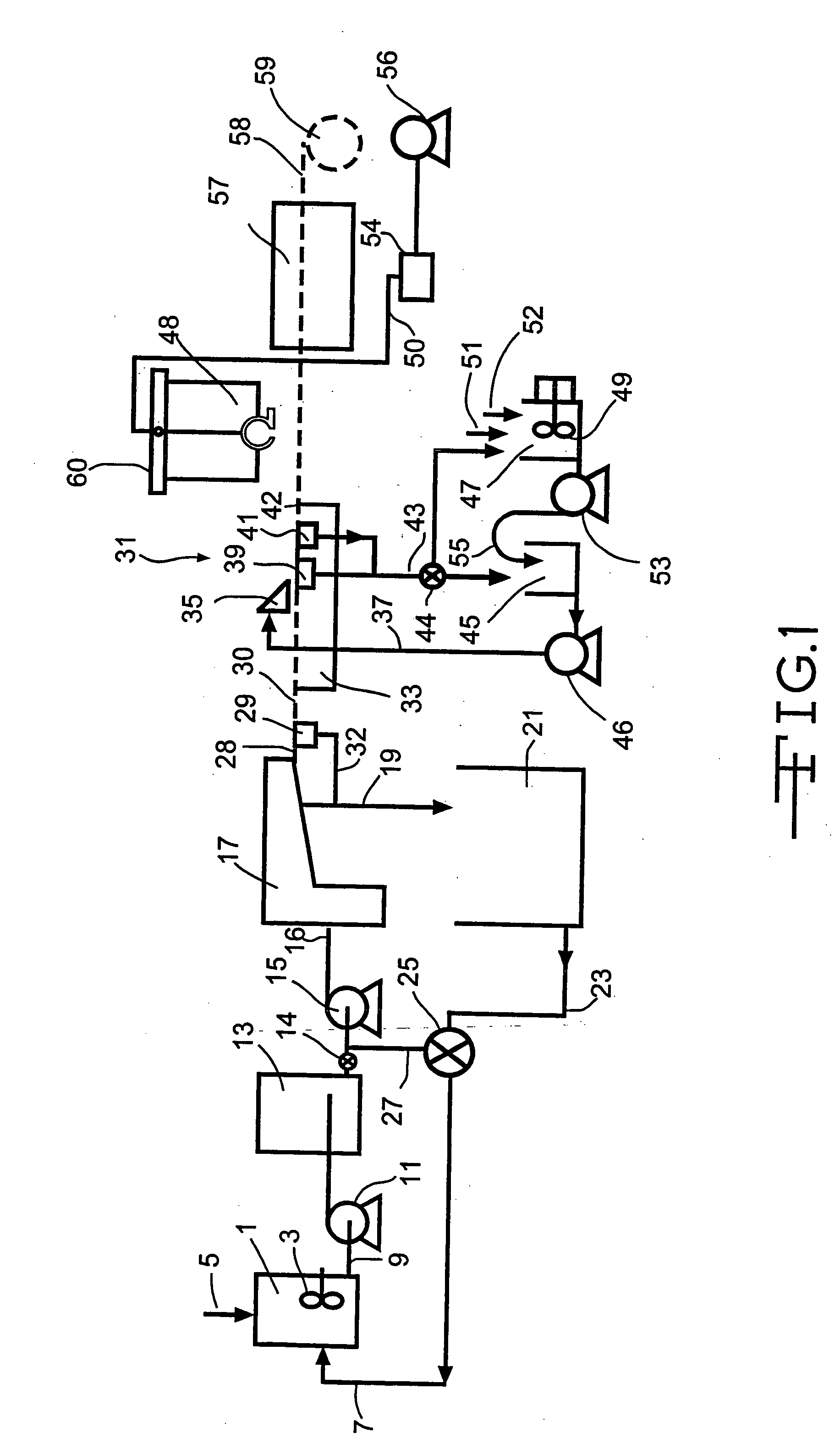
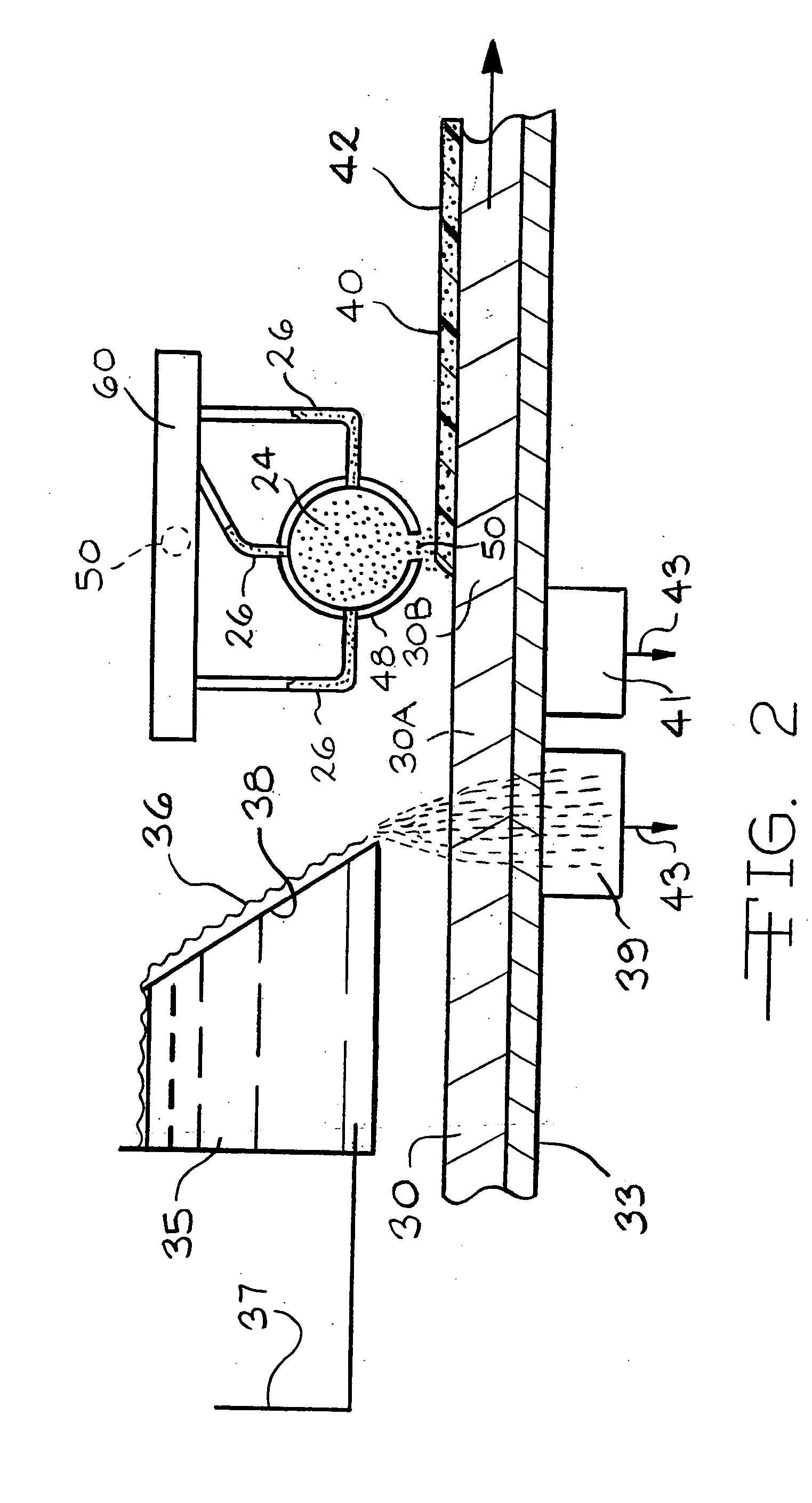
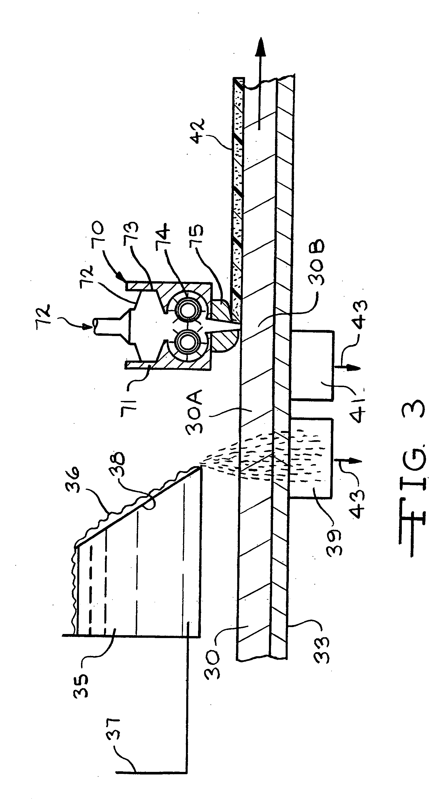
Image

Examples
example 1
[0048] A wet web was formed in a conventional wet process on a laboratory wet former simulating a Voith Hydroformer™ line as used and disclosed in U.S. Pat. Nos. 4,637,496 and 5,772,846 using M 117 glass fibers one inch long. A fiber slurry was prepared in a well known manner by adding one inch long E glass type M 117 wet chop glass fiber from Johns Manville International, Inc. having a silane containing chemical sizing on the surface, as is well known, to a known cationic white water containing Natrosol™ thickening agent available from Aqualon, Inc. of Wilmington, Del., and a cationic surfactant C-61, an ethoxylated tallow amine available from Cytec Industries, Inc. of Morristown, N.J., as a dispersing agent to form a fiber concentration of about 0.8 weight percent. After allowing the slurry to agitate for about 5 minutes to thoroughly disperse the fibers, the slurry was metered into a moving stream of the same whitewater to dilute the fiber concentration to a concentration averagi...
example 2
[0056] Another wet web was formed in the same conventional wet process on a laboratory wet former simulating a Voith Hydroformer™ line as used and disclosed in U.S. Pat. Nos. 4,637,496 and 5,772,846 as used in Example 1. A fiber slurry was prepared in a well known manner by adding 0.75 inch long E glass type K 117 wet chop glass fiber from Johns Manville International, Inc. having a silane containing chemical sizing on the surface, as is well known, to a known cationic white water containing Natrosol™ thickening agent available from Aqualon, Inc. of Wilmington, Del., and a cationic surfactant C-61, an ethoxylated tallow amine available from Cytec Industries, Inc. of Morristown, N.J., as a dispersing agent to form a fiber concentration of about 0.8 weight percent. After allowing the slurry to agitate for about 5 minutes to thoroughly disperse the fibers, the slurry was metered into a moving stream of the same whitewater to dilute the fiber concentration to a concentration averaging a...
example 3
[0066] Example 2 was duplicated except for the type of foam used and the basis weight of the finished mat that in this example was 64.3 gms / sq. meter. Also, an uncoated, bindered mat of the same kind as the bindered mat used to make the coated mat was made as a control. In this example a fluorpolymer was used. The fluorpolymer used was Sequapel NRL available from Omnova Solutions of Chester, S.C. The properties of fluorpolymer coated mat and the control mat were as follows:
[0067] Control mat LOI—27.6 percent
[0068] Coated mat LOI—29.1
[0069] Amount of foam addition—about 1.5 wt. percent of finished mat
[0070] Permeability of control mat—1.66 CMM / sq. meter
[0071] Permeability of coated mat—1.6 CMM / sq. meter
[0072] Dry tensile strength of control mat—39.6 kg / 7.62 cm width
[0073] Dry tensile strength of coated mat—33.2 kg / 7.62 cm width
[0074] Hot wet tensile of control mat—18.3 kg / 7.62 cm width
[0075] Hot wet tensile of coated mat—15.4 kg / 7.62 cm width
[0076] The coated mat was tested...
PUM
| Property | Measurement | Unit |
|---|---|---|
| density | aaaaa | aaaaa |
| density | aaaaa | aaaaa |
| viscosity | aaaaa | aaaaa |
Abstract
Description
Claims
Application Information