

Separator for fuel cell, method for producing the same, and fuel cell using the same
a separator and fuel cell technology, applied in the direction of cell components, non-metal conductors, conductors, etc., can solve the problems of complex production processes, high temperature and long time, and none of the above processes give a separator with sufficient performance, etc., to achieve good electroconductivity, excellent gas impermeability, and good mechanical properties. , the effect of retaining performance characteristics
- Summary
- Abstract
- Description
- Claims
- Application Information
AI Technical Summary
Benefits of technology
Problems solved by technology
Method used
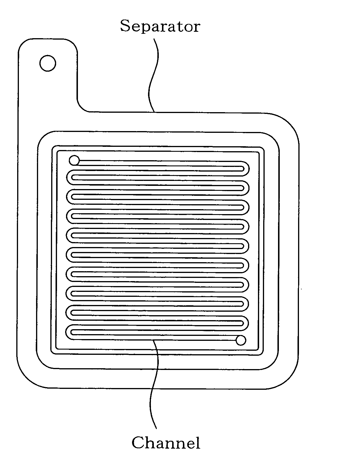
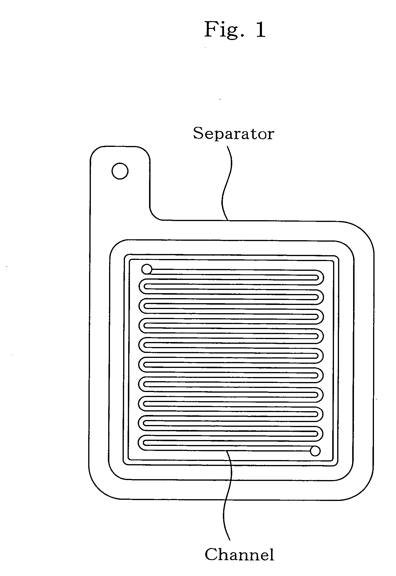
Image

Examples
synthesis example 1
Synthesis of Dihydrobenzoxazine Compound
[0096] A flask was charged with 1,4-dioxane and 2 mol of 37% formalin. While maintaining the mixture at 5° C. or less, 1 mol of aniline (a 1,4-dioxane solution) was added dropwise with stirring. Further, 1 mol of phenol novolac (a 1,4-dioxane solution) was added dropwise in the same manner. After completion of the addition, the resulting mixture was heated to reflux, and the reaction was continued for 6 hours at the same temperature. The solvent was then distilled off to thereby obtain a phenol novolac type dihydrobenzoxazine compound in which about 90% of the phenolic hydroxyl groups had been converted to dihydrobenzoxazine (a compound of formula (7); hereinafter “N1-a”).
preparation example 1
Preparation of Reaction Product of Alkanolamine with p-toluenesulfonic Acid (Curing Agent)
[0097] p-Toluenesulfonic acid (9.5 g (0.05 mol)) was added at room temperature to 5.26 g (0.05 mol) of diethanolamine or 3.8 g (0.05 mol) of isopropanolamine, to carry out reactions (hereinafter the reaction product of diethanolamine with p-toluenesulfonic acid being referred to as “cat. 1”, and the reaction product of isopropanolamine with p-toluenesulfonic acid as “cat. 2”).
examples 1 to 8
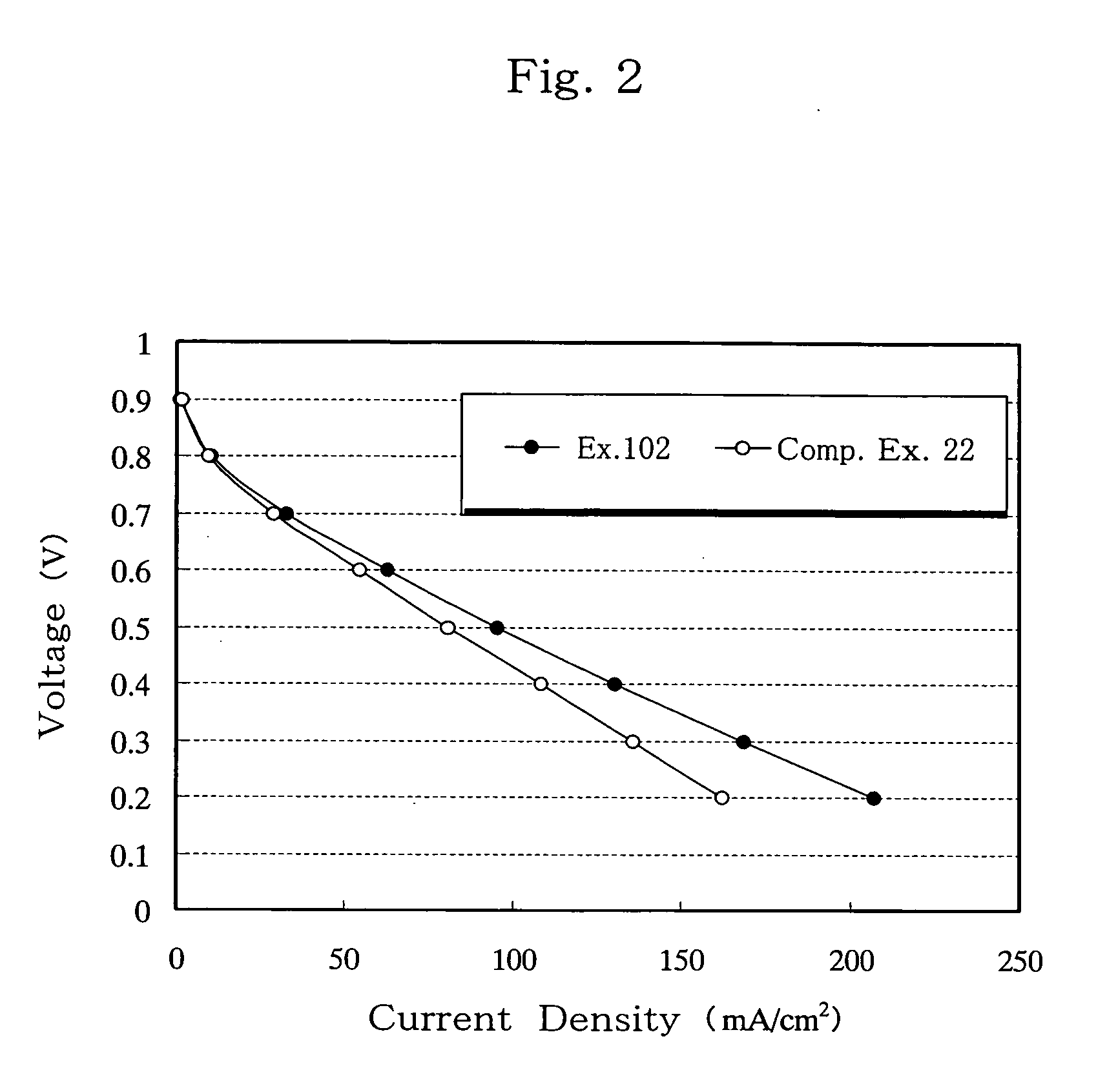
[0098] B-a or N1-a as a dihydrobenzoxazine compound (component a), 1,3-PBO, DGEBA or OCNE as a compound reactive with a phenolic hydroxyl group formed by opening of a dihydrobenzoxazine ring (component b), and cat. 1 or cat. 2 as a latent curing agent (component c) were melt-mixed at 130° C. in the ratios specified in Table 1, to obtain thermosetting resins. Specifically, equimolar amounts of components a and b were melt-mixed, and 10 parts by weight of component c was added to 100 parts by weight of components a and b combined. Thereafter, the thermosetting resin (a+b+c) and a graphite (GE-134) as an electroconductive material were mixed in a weight ratio of 20:80, solution-blended in acetone and thoroughly mixed in a mixer. The acetone was removed, and the resulting electroconductive resin composition was pulverized, tableted at room temperature, and compression-molded in a mold at 170° C. and 30 MPa for 10 minutes, to thereby obtain 1 mm-thick carbon moldings for use as fuel cell...
PUM
| Property | Measurement | Unit |
|---|---|---|
| Volume | aaaaa | aaaaa |
| Volume | aaaaa | aaaaa |
| Fraction | aaaaa | aaaaa |
Abstract
Description
Claims
Application Information