Valve bypass graft device, tools, and method

a valve bypass and graft technology, applied in the field of valve bypass graft devices, can solve the problems of inability to gain popularization among surgeons, excessive blood loss, potential stroke, etc., and achieve the effect of fast completion of the implant procedure, reliable and safe method, and no stopping or reducing blood flow through the aorta

Inactive Publication Date: 2005-07-07
CARDIOUS
View PDF8 Cites 79 Cited by
  • Summary
  • Abstract
  • Description
  • Claims
  • Application Information

AI Technical Summary

Benefits of technology

[0033] The primary object of the present invention is to provide an implantable device, the associated implant tools, and a reliable and safe method to alleviate the problems associated with a stenotic native aortic valve without replacing the diseased valve, without stopping the heart or lungs, without removing myocardial tissue, without excessive blood loss, and without disrupting flow or generating emboli in the aorta
[0034] Specifically, the invention has the following advantages:
[0037] b...

Problems solved by technology

Even though this first human use proved feasibility of the valved conduit device, the procedure did not gain popularity with surgeons because, precisely at that point in the evolution of surgical techniques, cardiopulmonary bypass methods were being perfected which led surgeons to select direct valve resection and replacement over Templeton's more radical valve bypass procedure.
Its known problems, namely excessive blood loss and potential stroke due to the need for cardiopulmonary support, have now been widely accepted because no better alternative has emerged for heart valve surgery.
One limitation of this approach is that the conduit needs to be in two pieces so that the catheter can be removed.
Khanna reported that one drawback to performing the procedure was the possibility that the Foley catheter may be cut, causing immediate deflation and rapid blood loss.
Although the surgeon's finger could be used to breach the hole or gap, excessive blood loss using this technique seemed possible if the balloon seal was not maintained (Khanna S K, et. al
Looking back on these early pioneering efforts, acceptance of this innovative technique in the 1960's and 1970's was most likely limited because t...

Method used


Image

  • Valve bypass graft device, tools, and method
  • Valve bypass graft device, tools, and method
  • Valve bypass graft device, tools, and method

Examples


Embodiment Construction

Structure

Valve / Conduit Implant

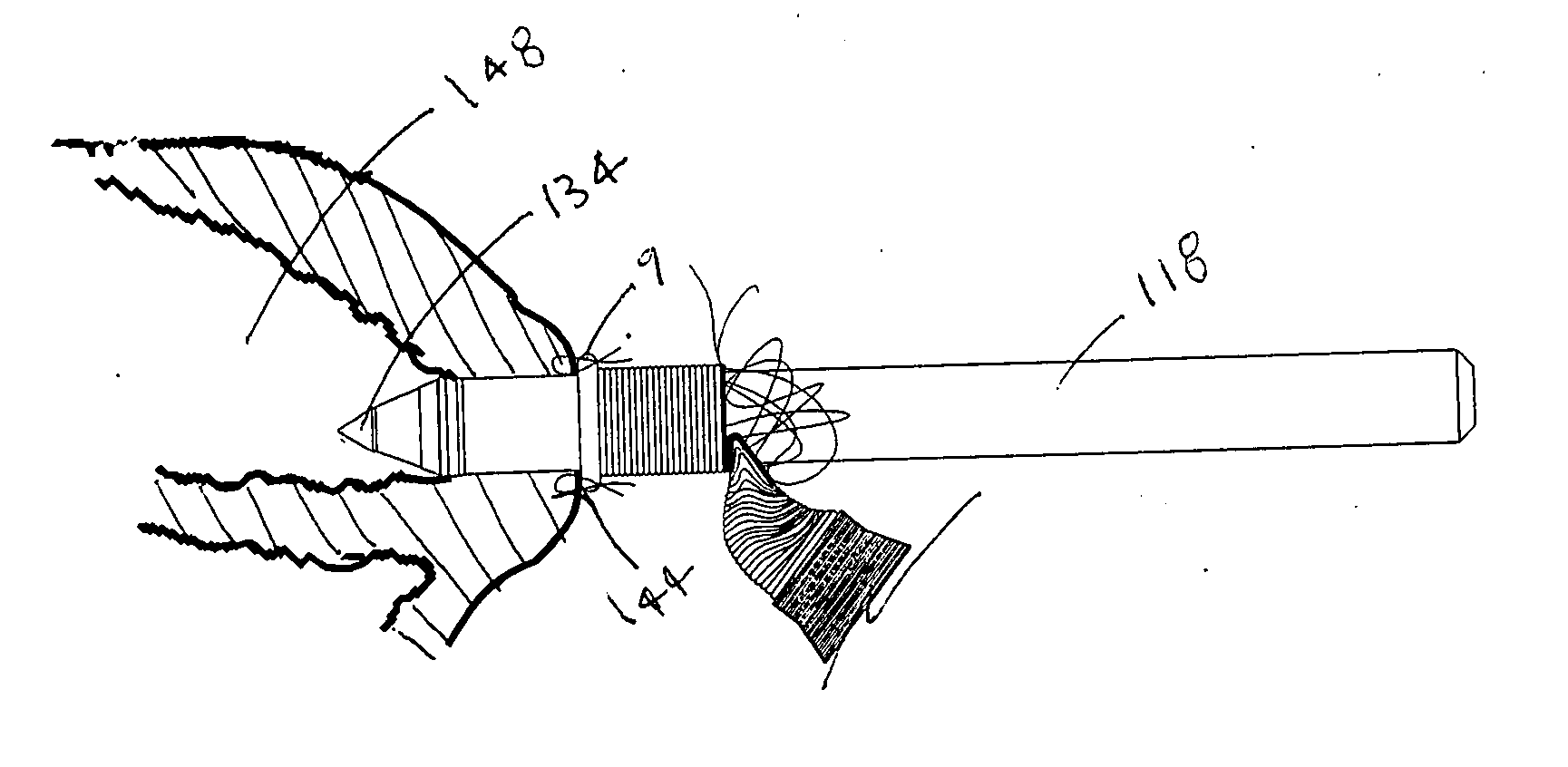
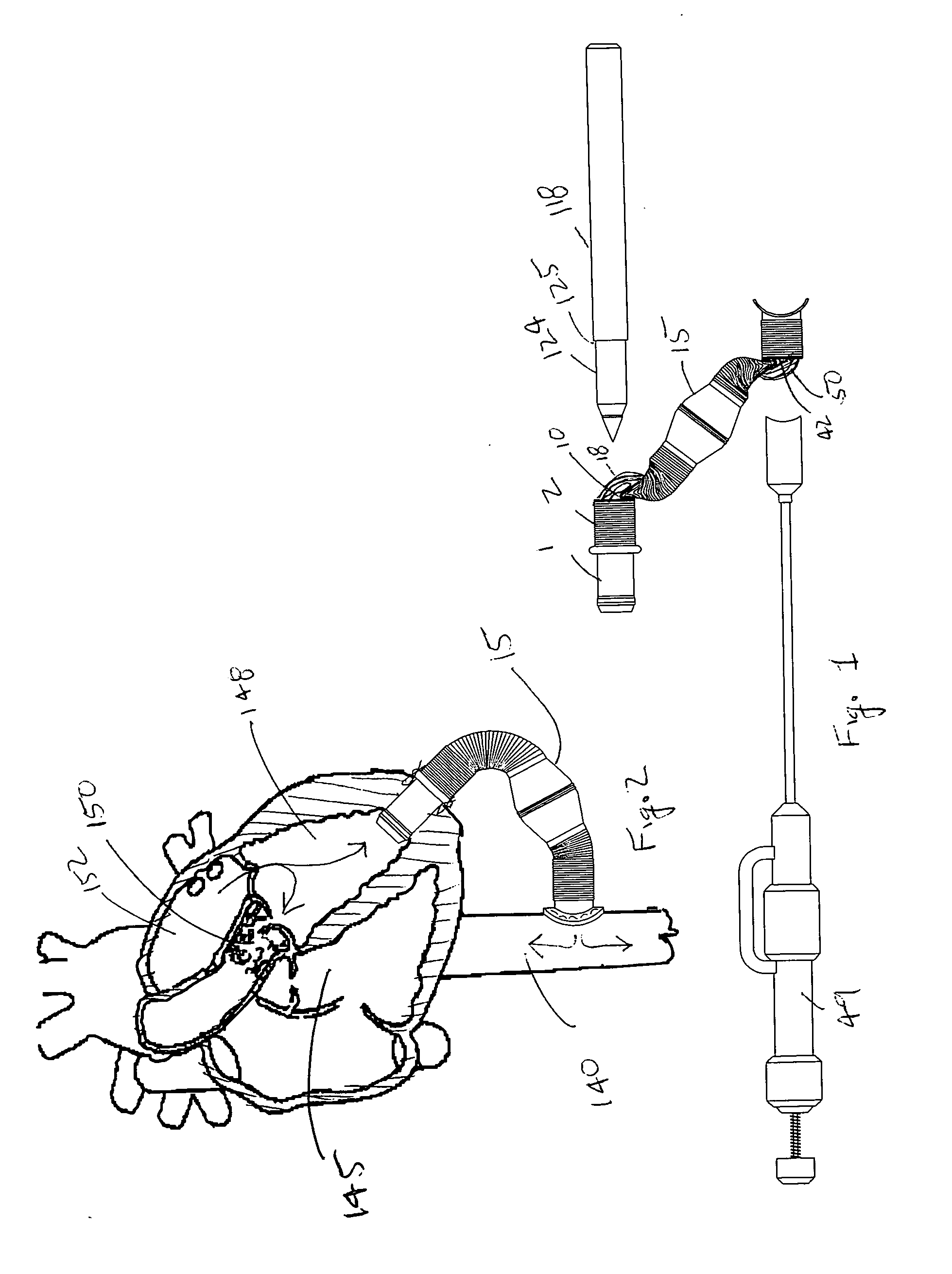
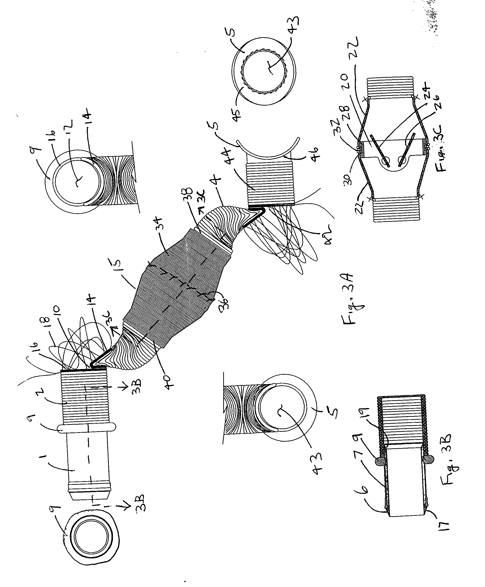
[0076] A preferred embodiment of a Valve / Conduit Implant 15 is shown in FIGS. 3A-C. The implant is comprised of five main assemblies as shown in FIG. 3A; a Ventricular Connector 1, a Ventricular Conduit Segment 2, a Valve Segment 3, a Aortic Conduit Segment 4, and an Aortic Cuff 5. The assemblies are integrated into one implant device called the Valve Bypass Conduit. The following is a more detailed description of each assembly.

[0077] The Ventricular Connector 1 is composed of two elements as shown in cross section in FIG. 3B; a Ventricular Orifice 6 and a Ventricular Cuff 7. The Ventricular Orifice 6 is cylindrically shaped and composed of a rigid biomaterial material such as stainless steel, titanium, or pyrolytic carbon. The internal diameter of the Ventricular Orifice in a preferred embodiment would be sized to have a cross sectional area of about 2 square centimeters, which equates to a diameter of about 16 millimeters. Depending on flow require...


PUM


Abstract

This invention relates to an implant, implant tools, and an implant technique for the interposition of an extracardiac conduit between the left ventricle of a beating heart and the aorta to form an alternative one-way blood pathway thereby bypassing the native diseased aortic valve. The implant consists of a hollow conduit having a first end opening, a second end opening, and a one-way valve located between the end openings. The valve is biased to allow one-way flow from the second end opening to the first end opening. A first slit opening is located between the first end opening and the valve and a second slit opening is located between the second end opening and the heart valve. The implant tools consist of a vessel wall cutting tool and a heart wall piercing and dilating tool. The vessel wall cutting tool is sized to closely fit through the implant's first slit opening and the first end opening. The heart wall piercing and dilating tool is sized to closely fit through the implant's second slit opening and the second end opening. The implant technique allows the surgeon to safely connect the implant between a heart chamber and a blood vessel without stopping the heart or impeding flow in the blood vessel.

Description

[0001] This application claims priority from provisional patent application U.S. Ser. No. 60 / 515,833 filed Oct. 30, 2003.BACKGROUND [0002] 1. Field of Invention [0003] This invention relates to an improved implant, improved implant tools, and an improved implant technique for the interposition of an extracardiac conduit between the left ventricle of a beating heart and the aorta to form an alternative one-way blood pathway thereby bypassing the native diseased aortic valve. [0004] 2. Clinical Need [0005] A reduction in the heart's cardiac output, that is, the reduced ability of the heart to output oxygenated blood from the left side of the heart can result from various abnormalities and diseases. In most cases, this reduction in output is due to aortic valve disease. The major type of aortic heart valve disease is valve stenosis. Stenosis involves the narrowing of the aortic outflow tract. The stenosis typically involves the buildup of calcified material on the valve leaflets, causi...

Claims


Application Information

Patent Timeline
IPC IPC(8): A61B17/00A61B17/11A61B17/34
CPCA61B17/3415A61B17/3468A61B2017/1135A61B2017/1107A61B2017/00252
Inventor POKORNEY, JAMES L.
Owner CARDIOUS
Why Eureka
Try Eureka