
Selectively light curable support members for medical devices

a technology of support members and medical devices, applied in the field of support members, can solve the problems of inconvenient operation, laborious and difficult to perfect steps of collapsing and placing a stent over a balloon, and the tendency of self-expanding stents to lack sufficient strength to maintain their expanded shap

Inactive Publication Date: 2005-07-07
BOSTON SCI SCIMED INC
View PDF99 Cites 42 Cited by
  • Summary
  • Abstract
  • Description
  • Claims
  • Application Information

AI Technical Summary

Benefits of technology

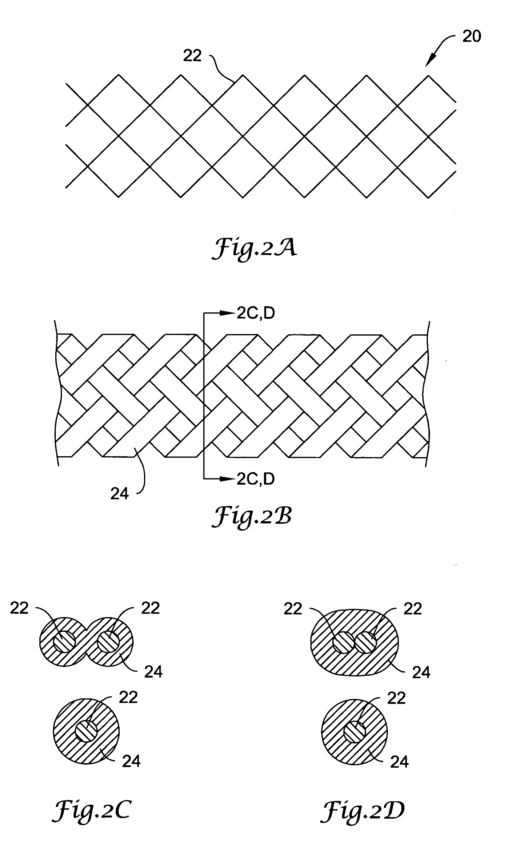
[0006] One embodiment of the invention includes a catheter shaft section comprising a support member. The support member may be formed using any suitable structure, i.e., tubes, braided, coiled, or woven designs, or other structures that use one or more strands to make a tubular member. At least one strand used in making the support member comprises a fiber coated with a resin comprising a photosensitive polymerizable composition (PPC). To facilitate coating with the resin, the fiber may be treated by a plasma treatment or other treatment to improve adhesion with the PPC. A single fiber may comprise a group of filaments. The filaments may be individually short in length, but part of a long or endless fiber. The plasma treatment, in this instance, will facilitate the coating of each of the filaments and to fill the space between filaments to bind together and form a fiber.
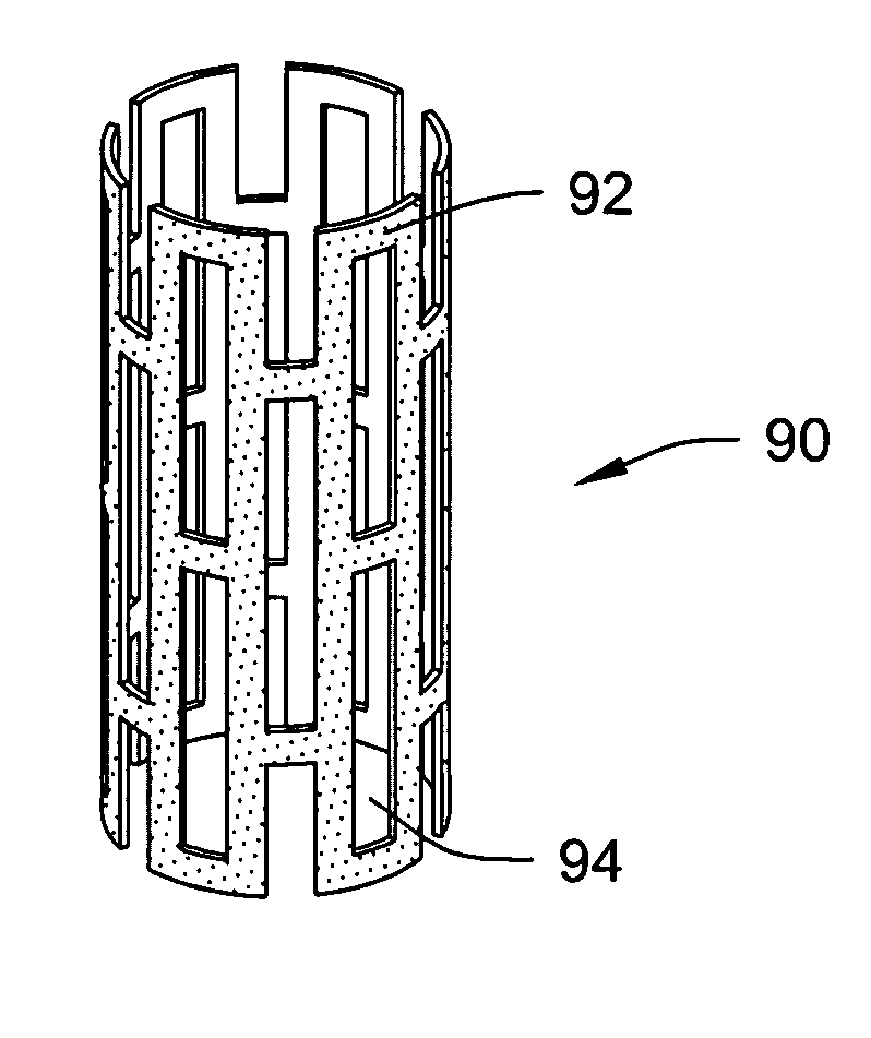
[0011] An illustrative method embodiment includes providing a stent having portions comprising fibers coated by a PPC resin. The stent may be collapsed onto a balloon or other expandable catheter by folding at least some of the PPC resin coated fibers. The method may further include advancing the stent to a desired location in a bodily lumen and expanding the stent at the desired location. The stent may then be exposed to light to cause at least some of the PPC resin to polymerize, causing the stent to stiffen in its expanded state. Allowing the vessel time to reshape the stent, prior to stiffening, to a more preferred shape helps overcome the issue of shape mismatch between the expanded balloon shape and vessel anatomy. This is a definite advantage over stent structures unable to be stiffened in-vivo.

Problems solved by technology

However, this thermal process can also affect other properties of the thermoplastic (for example, brittleness or tensile strength) or the shape of the shaft or of a lumen therethrough, and the procedure can be imprecise.
Further, the steps of collapsing and placing a stent over a balloon can be labor intensive and difficult to perfect.
Self-expanding stents have a tendency, however, to lack sufficient strength to maintain their expanded shape.
However, a metallic stent is typically not conducive to the use of MRI diagnostic techniques that are used for a number of reasons.
Meanwhile, nonmetallic stents often lack desired properties (i.e., strength) that can make them usable for this purpose.
Another limitation with respect to stent technology is that existing stents are made with materials that are relatively stiff.
This makes placement of the stent in a desired location difficult.

Method used


Image

  • Selectively light curable support members for medical devices
  • Selectively light curable support members for medical devices
  • Selectively light curable support members for medical devices

Examples


Embodiment Construction

[0027] The following detailed description should be read with reference to the drawings. The drawings, which are not necessarily to scale, depict illustrative embodiments and are not intended to limit the scope of the invention. As used herein, the term “light” includes radiation of any wavelength and is not limited to visible, infrared, or ultraviolet wavelengths.

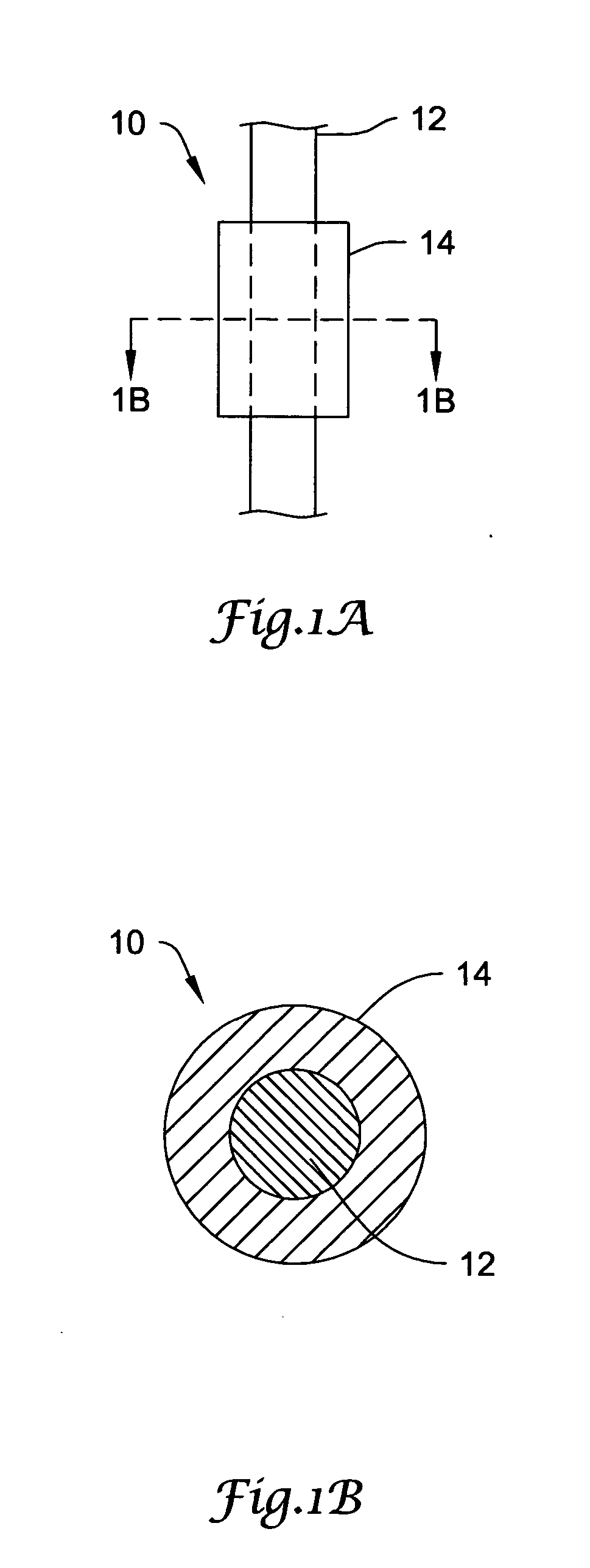
[0028]FIGS. 1A-1B illustrate a strand for use in catheter support members and stents, with FIG. 1B being a cross section along line B-B in FIG. 1A. The strand 10 includes a fiber 12 and a coating 14. The fiber 12 may be metal or non-metallic, and preferably is a polymer fiber. One suitable polymer is a high strength polyethylene fiber sold under the brand Spectra™ by Honeywell®, which is used in Spectra Shield® protective (i.e., bulletproof) materials. Ceramic fibers from 3M or Nextell could also be utilized. Preferably, the coating 14 is a photosensitive polymerizable composition (PPC) which, when exposed to a certain wa...


PUM

PropertyMeasurementUnit
axial lengthaaaaaaaaaa
flexibilityaaaaaaaaaa
stiffnessaaaaaaaaaa

Abstract

Methods of forming support layers for use in catheters using having a support layer included, and stents incorporating coatings of photosensitive polymerizable resins and stents including fibers coated with photosensitive polymerizable resins. A fiber is coated with a PPC resin and incorporated into a support structure for a catheter. Portions of the PPC are polymerized by exposure to light of a desired wavelength, causing increased rigidity and strength to the polymerized portions. As the PPC is polymerized, the fibers coated by the PPC resins become stronger and change the flexibility of devices incorporating such fibers. Additional embodiments include stents incorporating PPC coatings and methods of using such stents, including polymerizing a PPC coating after inserting a self-expanding or balloon-expandable stent.

Description

FIELD OF THE INVENTION [0001] The present invention relates generally to support members used to provide improved properties to catheters, stents. More particularly, the present invention relates to support structure designs wherein the stiffness and / or shape of the support structure can be altered due to selective curing by light. BACKGROUND OF THE INVENTION [0002] Many medical procedures include the insertion of a catheter into a lumen of a living body. Catheters are commonly used in procedures in the vascular system such as angiography, angioplasty, and other diagnostic or interventional procedures. In many of these procedures, the catheter must travel a tortuous path in order to reach the point of treatment. In order to aid in this travel through a body lumen, it is often desirable to have variable stiffness along the shaft of the catheter. With balloon catheters, various material transitions may be used to effect variable stiffness. Alternatively, a stiffening support structure...

Claims


Application Information

Patent Timeline
Patent Type & Authority Applications(United States)
IPC IPC(8): A61L29/14
CPCA61L29/14A61F2/88A61F2/90A61M25/005A61F2002/072A61F2/945A61M25/0012A61M25/0041A61M2025/0063
Inventor HEGGESTUEN, JAMESHOLMAN, THOMAS J.WEBER, JAN
Owner BOSTON SCI SCIMED INC
Learn More