Molded fiber manufacturing

a technology of molded fibers and molded bodies, applied in the field of molded fiber manufacturing, can solve the problems of reducing the adhesion of the molded fiber shaped body to the thermo-, and the ineffective vacuum dewatering, so as to reduce the amount of water, reduce the energy consumption of manufacturing, and reduce the effect of thermal energy

Inactive Publication Date: 2005-07-14
GRENIDEA TECH PTE
View PDF4 Cites 62 Cited by
  • Summary
  • Abstract
  • Description
  • Claims
  • Application Information

AI Technical Summary

Benefits of technology

[0016] Yet another objective of the invention is to reduce the energy consumption in manufacturing molded fiber shaped body. Most of the energy is consumed in the thermo-curing process where large amount of thermal energy is used to dry excessive water in the wet fiber shaped body. It is understood that reducing the amount of water in the wet fiber shaped body will reduce the thermal energy. The present invention optimize the use of mechanical dewatering means to reduce the water content in the wet fiber shaped body formed by the vacuum-forming process. The vacuum-forming process uses a pair of matching molds namely top and bottom molds. The top and bottom molds are opened to allow the fiber slurry to be added. Water in the fiber slurry is extracted away by vacuum means through the porous mold inserts to form a uniform layer of wet fiber shaped body on the bottom mold. In order to extract more water out of the wet fiber shaped body, the top mold and bottom mold are closed and sealed to prevent air infiltration during vacuum dewatering of the wet fiber shaped body. Simultaneously, the top mold and bottom molds apply a slight pressure to the wet fiber shaped body. The mechanical dewatering process stops when the water content in the wet fiber shaped body reaches some pre-determined level, usually in the range of 20% to 50% (wt). It is to be noted that if the top and bottom molds are not sealed when closed, vacuum dewatering will not be effective as ambient air instead of water in the wet fiber shaped body will be extracted.

Problems solved by technology

The air pockets reduce the adhesion of the molded fiber shaped body to the thermo-curing mold.
It is to be noted that if the top and bottom molds are not sealed when closed, vacuum dewatering will not be effective as ambient air instead of water in the wet fiber shaped body will be extracted.

Method used


Image

  • Molded fiber manufacturing
  • Molded fiber manufacturing
  • Molded fiber manufacturing

Examples


Embodiment Construction

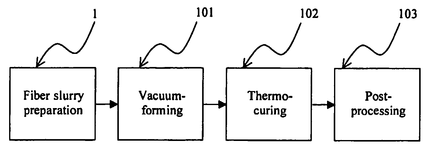
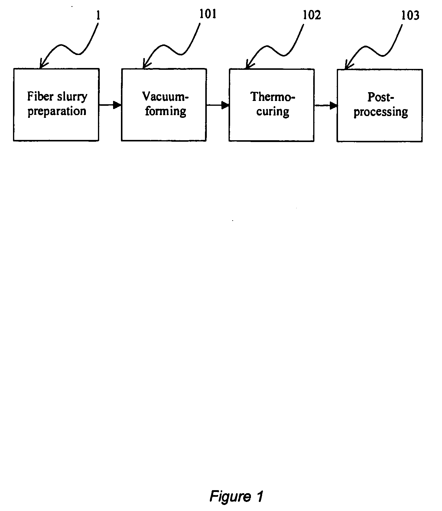
[0025] The improved molded fiber shaped body manufacturing process consists of four major steps. These are (1) fiber slurry preparation; (2) vacuum-forming and (3) thermo-curing and (4) post-processing.

[0026] The manufacturing process begins with the preparation of fiber slurry. Sufficiently refined plant fibers such as fibers obtained from palm oil, coconut coir, hemp, kenaf and other fibrous plants are added to a mixer tank. The mixer tank can be pre-filled with water or water can be added simultaneously with the fiber. The amount of fiber is 0.1 to 5 percent (wt) with respect to 99.9 to 95 percent (wt) of water. The fibers are agitated by an agitator such as an impeller to disperse them in the water. The low consistency fiber mixture is sufficiently agitated until a homogenous slurry is obtained. Water based adhesive binder is then added to the mixer tank and the entire mixture is continuously agitated. The agitation action causes the adhesive binder to attach to the fiber. Func...


PUM

PropertyMeasurementUnit
size distributionaaaaaaaaaa
roughnessaaaaaaaaaa
roughnessaaaaaaaaaa

Abstract

Molded fiber products using agriculture residues are economical and environmentally beneficial. Molded fiber manufacturing is different from molded pulp. The present invention discloses a method of and an apparatus for the manufacturing of molded fiber shaped body (10) using low consistency fiber slurry (12) subject to vacuum-forming and thermo-curing. The use of porous material as mold inserts for both vacuum-forming (101) and thermo-curing (102) stations provides improved productivity and enables ease of mold release. The incorporation of self-cleaning techniques further ensures consistent performance of the manufacturing system.

Description

[0001] This invention relates to a method of and an apparatus for improving the manufacturing of molded fiber shaped body. BACKGROUND [0002] Products made of molded fiber are environmental friendly. Raw materials for manufacturing molded fiber products are derived from agriculture residues which are usually treated as waste. Unlike pulp, fibers from agriculture residues do not need to be rigorously treated before they are used. When molded fiber products are disposed, they are biodegradable and are emission neutral. [0003] Molded fiber shaped bodies can be used as packaging for food, industrial goods, consumer products and many others. It has very good cushioning property and is ready to be used without the need to cut, bend and fold. It is also light and stackable which reduce storage and shipping space. Molded fiber packaging is a cost economical and environmental friendly choice to replace existing plastics and paper packaging. [0004] Vacuum thermoforming method using low-consist...

Claims


Application Information

Patent Timeline
Patent Type & Authority Applications(United States)
IPC IPC(8): D21B1/00D21H17/16D21H17/17D21H21/16D21H23/04D21J3/10D21J7/00
CPCD21B1/00D21H17/16D21J7/00D21H21/16D21H23/04D21H17/17
Inventor TOH, PENG SENGXU, YANSLOW, MENG LEE
Owner GRENIDEA TECH PTE
Why Eureka
Try Eureka