Switching pattern ac induction motor

Active Publication Date: 2005-07-14
HUANG YOUGUO +1
View PDF9 Cites 13 Cited by
  • Summary
  • Abstract
  • Description
  • Claims
  • Application Information

AI Technical Summary

Benefits of technology

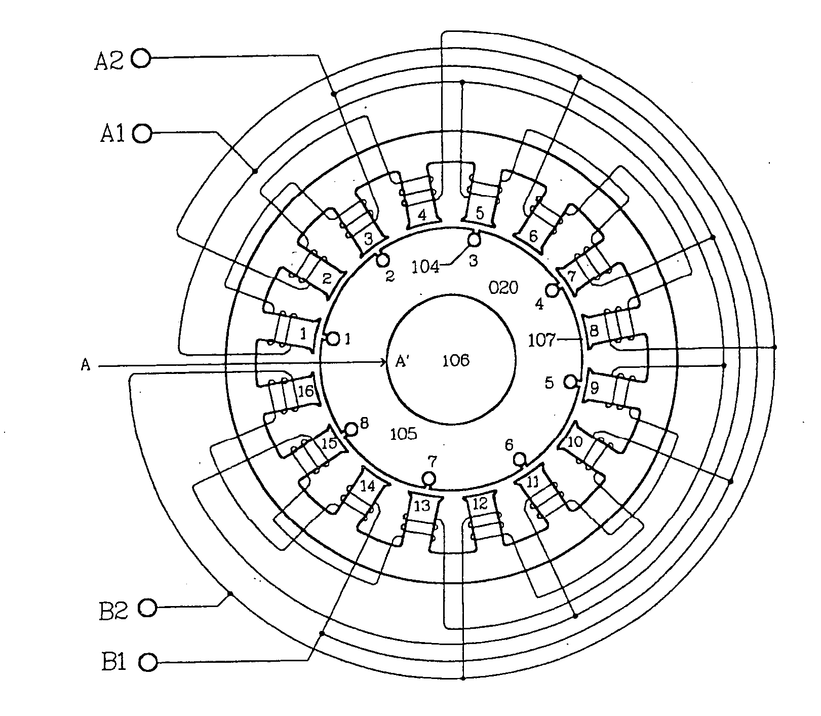
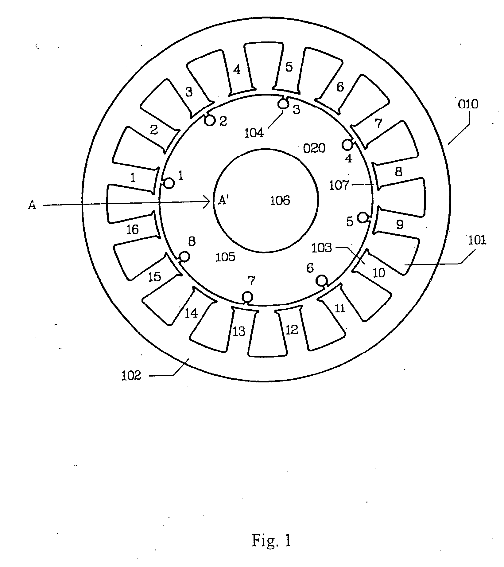
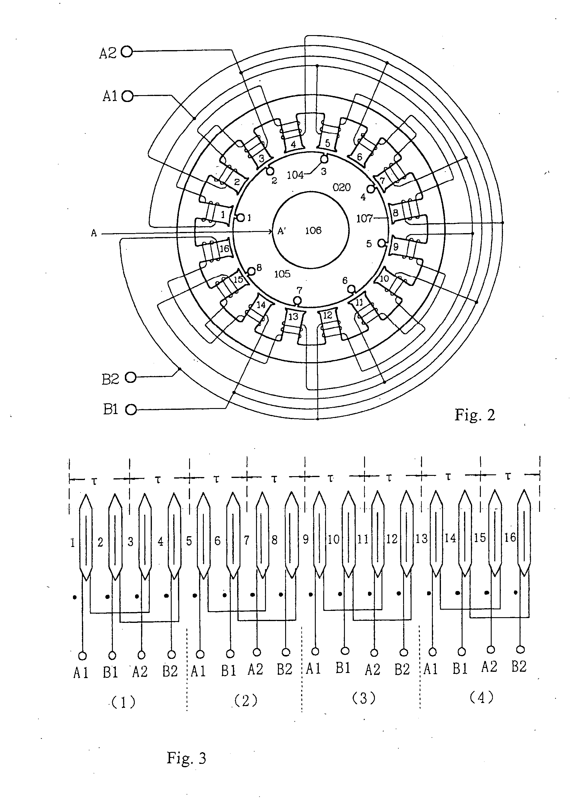
[0009] The most essential innovation of the novel motor according to the present invention is the innovation of the excitation technique, i.e. it is excited by sine wave pulse modulated voltages within the frequency range of voice or ultrasonic, when the excitation windings in the stator are excited, the required pulsating alternating rotating magnetic field is generated in the air gap between the stator and the rotor, induced current is generated in the conducting bars on the rotor, and, the torque of electromagnetic force in such a pulsating alternating rotating magnetic field is applied on the conducting bars, so that the rotor of the motor rotates. Supposing the frequency of the modulating sine wave voltages is F1, the frequency of the modulating square wave voltage is F2, when the motor operates, the rotating speed of the pulsating alternating rotating magnetic field only depends on the frequency F1 of the modulating sine wave voltages, and is independent of the frequency F2 of the modulating square wave voltage, thereby the speed regulation of the motor can be achieved by changing the frequency F1 of the modulating sine wave voltages with a control circuit. Since the pulse frequency of the sine wave pulse modulated excitation v

Problems solved by technology

However, since the actually required operating speed is typically much lower than the rotating speed of the motor, and because of the resistance characteristic of the excitation windings and the torque requirement of the motor, such as the torque of the AC asynchronous motor is somewhat low during low-speed running, sometimes a lower rotating speed can not be obtained by decreasing the excitation

Method used


Image

  • Switching pattern ac induction motor
  • Switching pattern ac induction motor
  • Switching pattern ac induction motor

Examples


Embodiment Construction

[0022]FIG. 1 shows a transverse sectional view of the stator and the rotor in a two-phase motor with 16 grooves and 4 pairs of poles, wherein “010” is a stator core with a shape of hollow cylinder, “101” are stator grooves penetrating along the axial direction, “102” is a stator yoke, “103” are stator teeth distributed in an identical angle and extending inward along the radial direction, the stator grooves and the stator teeth are arranged alternatively surrounding the internal surface, “020” is a rotor having a cylindrical surface, “104” are conducting bars distributed in parallel with equal intervals along the cylindrical surface of the rotor core of the motor, the conducting bars and the conducting rings (not shown in the drawings) located at the two end-faces of the cylinder are welded to be a metal inductor like a squirrel cage structure, “105” is a rotor core, “106” is a rotor shaft, “107” is the air gap between the rotor and the stator, the rotor shaft is supported by a roto...


PUM


Abstract

Both the stator core and the rotor core of a switching pattern AC induction motor are fabricated by soft magnetic material laminations or ferrite material, etc., both of which have corresponding frequency characteristic. The rotor is a squirrel cage rotor. Switching pattern excitation is adopted in the stator pole, of which the excitation voltage is sine wave pulse width modulated or sine wave pulse amplitude modulated within the frequency range of voice and ultrasonic. Under the condition of the same power output, the present motor reduces its size and mass to a fraction of or tenth of that of an ordinary one. Meanwhile, it reduces the cost of manufacture. It realizes stepless speed regulating from zero to several thousand rpm while keeping well mechanical characteristic performance.

Description

TECHNICAL FIELD [0001] The present invention relates to a novel motor, more particularly, to a switching pattern AC induction motor within the frequency range of voice and ultrasonic. BACKGROUND ART [0002] Existing AC induction motor, which is mainly squirrel cage type AC asynchronous induction motor, has the advantages of simple structure, low cost and larger output torque as compared with brush DC motor. Such a motor is typically excited with continuous two phases of sine wave voltages with a phase difference of 90° or three phases of sine wave voltages with a phase difference of 120°. A continuous sine wave rotating magnetic field is generated in the air gap between the stator and the rotor, which causes the squirrel cage type rotor rotating. The rotating speed of the motor can be approximately calculated by the rotating speed formula for the rotating magnetic field: n=60*f1 / p, where p is the number of pole pairs of the stator in the motor, f1 is the frequency of the excitation A...

Claims


Application Information

Patent Timeline
IPC IPC(8): H02K3/28H02K17/12H02K17/16
CPCH02K3/28H02K17/16H02K17/12H02P2207/01H02P2209/09Y10S388/912
Inventor HUANG, YOUGUOHUANG, WEI
Owner HUANG YOUGUO
Why Eureka
Try Eureka