Adaptive channel equalization technique and method for wideband passive digital receivers

a wideband, digital receiver technology, applied in the field of passive digital receivers, can solve problems such as variations in the transfer function characteristics, and achieve the effect of minimizing digital receiver signal measurement distortion and minimizing passive digital receiver signal distortion

Inactive Publication Date: 2005-07-14
L 3 COMM INTEGRATED SYST +1
View PDF16 Cites 21 Cited by
  • Summary
  • Abstract
  • Description
  • Claims
  • Application Information

AI Technical Summary

Benefits of technology

[0006] The present invention is an adaptive channel equalization technique and method for wideband passive receivers. The adaptive equalization method and technique of the present invention, as described in more detail below, provides a solution that reduces and tends to minimize the passive digital receiver signal distortions. This equalization architecture provides an adaptive equalization solution for a wideband passive channel that receives unknown signals from the RF environment both temporally and spectrally. A wideband chirp signal or calibration signal is periodically injected to capture the spectral response of the receiver channel as it varies from the distortions induced over time and temperature for synthesis of equalization filter coefficients. Thus, the channel equalization is performed independent of receiver signal source and is employed to minimize digital receiver signal measurement distortions across the passband by providing an equalization filter whose magnitude and phase response compensates for the channel distortions of the passive data collection system. In operation, magnitude and phase response of the equalization filter cascades with the channel to produce an overall transfer function that is linear in phase and as close to unity magnitude as realistically possible.

Problems solved by technology

More particularly, the distortions can include distortions inherent to analog circuitry within the receiver system that may cause variations in the transfer function characteristics due to internal or external operational conditions.

Method used


Image

  • Adaptive channel equalization technique and method for wideband passive digital receivers
  • Adaptive channel equalization technique and method for wideband passive digital receivers
  • Adaptive channel equalization technique and method for wideband passive digital receivers

Examples


embodiment 100

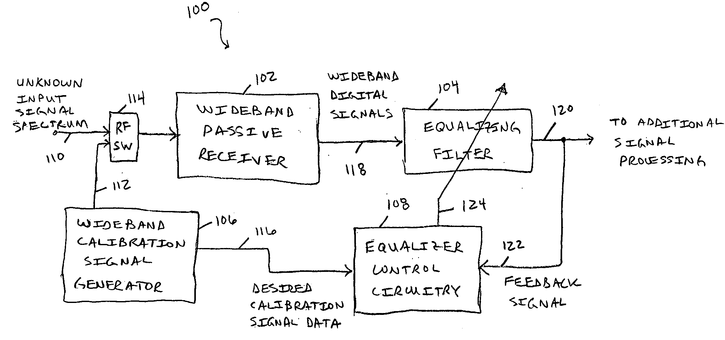
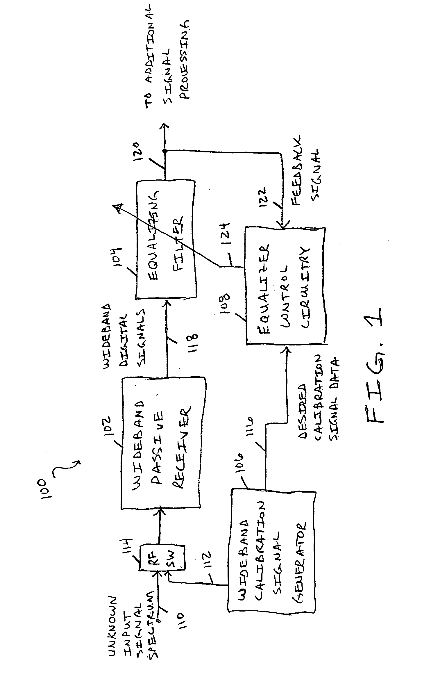
[0017]FIG. 1 is a block diagram of an embodiment 100 for a wideband passive digital receiver including an adaptive channel equalization filter 104 that uses a wideband calibration signal 112. As depicted, the receiver system 100 includes a wideband passive receiver 102, an equalization filter 104, equalizer control circuitry 108, a wideband calibration signal generator 106, and an RF switch (RF SW) 114. The input signal is typically a radio-frequency spectrum from unknown signal sources. This unknown input signal spectrum is processed by the wideband passive digital receiver 102 and the equalizing filter 104 to produce digital output signals 120 that can be subjected to further desired processing. The adaptive channel equalization filter 104 and the novel calibration technique of the present invention that utilizes a wideband calibration signal 112 allows for equalization of tuning errors induced by the receive path circuitry itself across the wideband range of the receiver 102. In ...

embodiment 200

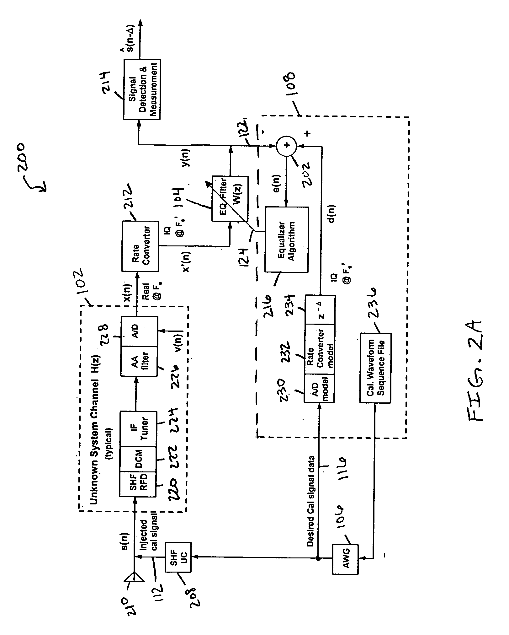
[0024]FIG. 2A is a more detailed block diagram of an embodiment for a wideband passive digital receiver including an equalization filter that uses a wideband calibration signal and where the input signal spectrum is not known to the receiver system. In particular, embodiment 200 includes a receiver 102 with an unknown system channel transfer function H(z), a sample rate converter 212, a signal detection and measurement block 214, an equalization (EQ) filter 104 with a filter transfer function W(z), equalizer control circuitry 108, a calibration chirp signal generator (AWG) 106, and a super high-frequency, RF up-converter (SHF UC) 208. The receiver 102 includes an SHF RF distribution Network (RFD) 220, a down conversion module (DCM) 222, an IF tuner 224, an anti-aliasing (AA) filter 226 and an analog-to-digital (A / D) converter 228. System noise is represented by signals v(n). The equalizer control circuitry includes an A / D converter 230 that is a model of A / D converter 228, a rate co...

embodiment 300

[0055] To describe the embodiment 300 of FIG. 3 in more detail, this embodiment depicts a block diagram of a BLMS adaptive equalizer implementation for use in a DSP processor or FPGA firmware type application. The first n=0:N-1 values of x(n) and d(n) are input to initiate the equalization process of the data. Any DC bias is removed from the x(n) and d(n) values input followed by magnitude normalization. The x(n) values are then loaded into the XL,N matrix composed of L shift registers, each of depth N where the oldest value is the rightmost column. The first row is the oldest group of N values and the last row is the newest group of N values. The input d(n) values are delayed by N / 2 samples (for example, with the insertion of N / 2 zeros) in order to align d(n) with the x(n) data. The initial N values of d(n) input are discarded. The block processing of L samples per block now begins (k=0). The next L samples are input and buffered for x(n) and d(n) to create the matrices X(k=0) and ...


PUM


Abstract

An adaptive channel equalization technique and method for wideband passive receivers is disclosed that reduces and tends to minimize distortions caused by circuitry within passive digital receivers. This equalization architecture provides an adaptive equalization solution for a wideband passive channel that receives unknown signals from the RF environment both temporally and spectrally. A wideband chirp signal or calibration signal is periodically injected to capture the spectral response of the receiver channel as it varies from the distortions induced over time and temperature for synthesis of equalization filter coefficients. Thus, the channel equalization is performed independent of receiver signal source and is employed to minimize digital receiver signal measurement distortions across the passband by providing an equalization filter whose magnitude and phase response compensates for the channel distortions of the passive data collection system.

Description

RELATED APPLICATIONS [0001] This application claims priority to the following co-pending provisional application: Provisional Application Ser. No. 60 / 536,294, which was entitled “ADAPTIVE CHANNEL EQUALIZATION TECHNIQUE AND METHOD FOR WIDEBAND PASSIVE DIGITAL RECEIVERS” and was filed on Jan. 14, 2004.GOVERNMENT RIGHTS [0002] This invention was made with United States Government support from the Department of the Air Force under Contract No. F33657-00-G-4029. The Government has certain rights in this invention.TECHNICAL FIELD OF THE INVENTION [0003] This invention relates to techniques and architectures for reception of electromagnetic radiation by receivers and, more particularly, passive digital receivers. BACKGROUND [0004] Receiver signal paths, or channels, of electronic data collection systems (such as airborne electronic receiver systems for unknown input signal spectrums) are often prone to multiple, dynamic sources of distortion that color the channel due to a temperature-time...

Claims


Application Information

Patent Timeline
Patent Type & Authority Applications(United States)
IPC IPC(8): H03K5/159H04L25/03
CPCH04L25/03133H04L2025/03757H04L2025/03617H04L2025/03477
Inventor REICHARD, TIMOTHY D.
Owner L 3 COMM INTEGRATED SYST
Why Eureka
Try Eureka