Energy device

a technology of energy devices and capacitors, applied in the direction of capacitor collector combinations, electric vehicles, vehicle components, etc., can solve the problems of low energy density, low input-output performance of secondary batteries, and inferior charge-discharge performance of secondary batteries under a large current, so as to secure the effect of using capacitors more conspicuously and excellent output performan

Inactive Publication Date: 2005-07-14
HITACHI LTD
View PDF0 Cites 30 Cited by
  • Summary
  • Abstract
  • Description
  • Claims
  • Application Information

AI Technical Summary

Benefits of technology

[0010] Note that, the terms “faradaic” and “non-faradaic” are broken down into two patterns as “faradaic” and “non-faradaic” in the types of batteries and the forms of energy storage. Meanwhile, since the present invention makes it possible to concentrate a layer wherein non-faradaic reaction occurs on the side closer to the opposed electrode, it is thought that the present invention can secure the effect of using a capacitor more conspicuously. Here, in the present invention, it is preferable that the area ratio of the portion exposed to the side of the opposed electrode of a layer wherein non-faradaic reaction occurs is from 30 to 100%.
[0011] By applying a configuration according to the present invention to an energy device, an energy device excellent in output performance particularly at a low temperature can be obtained.

Problems solved by technology

However, a secondary battery is inferior in charge-discharge performance under a large current and, in particular, the input-output performance thereof lowers conspicuously at a low temperature.
Meanwhile, the problem of an electric double layer capacitor has been that it shows a low energy density.
Moreover, in the case of mixing activated carbon that is used as a material of an electric double layer capacitor in the positive electrode of a lithium secondary battery in the interior thereof, since the amount of mixed activated carbon is hardly increased and the capacity of the capacitor is small, a sufficient improvement is not secured.

Method used


Image

  • Energy device
  • Energy device
  • Energy device

Examples


example 1

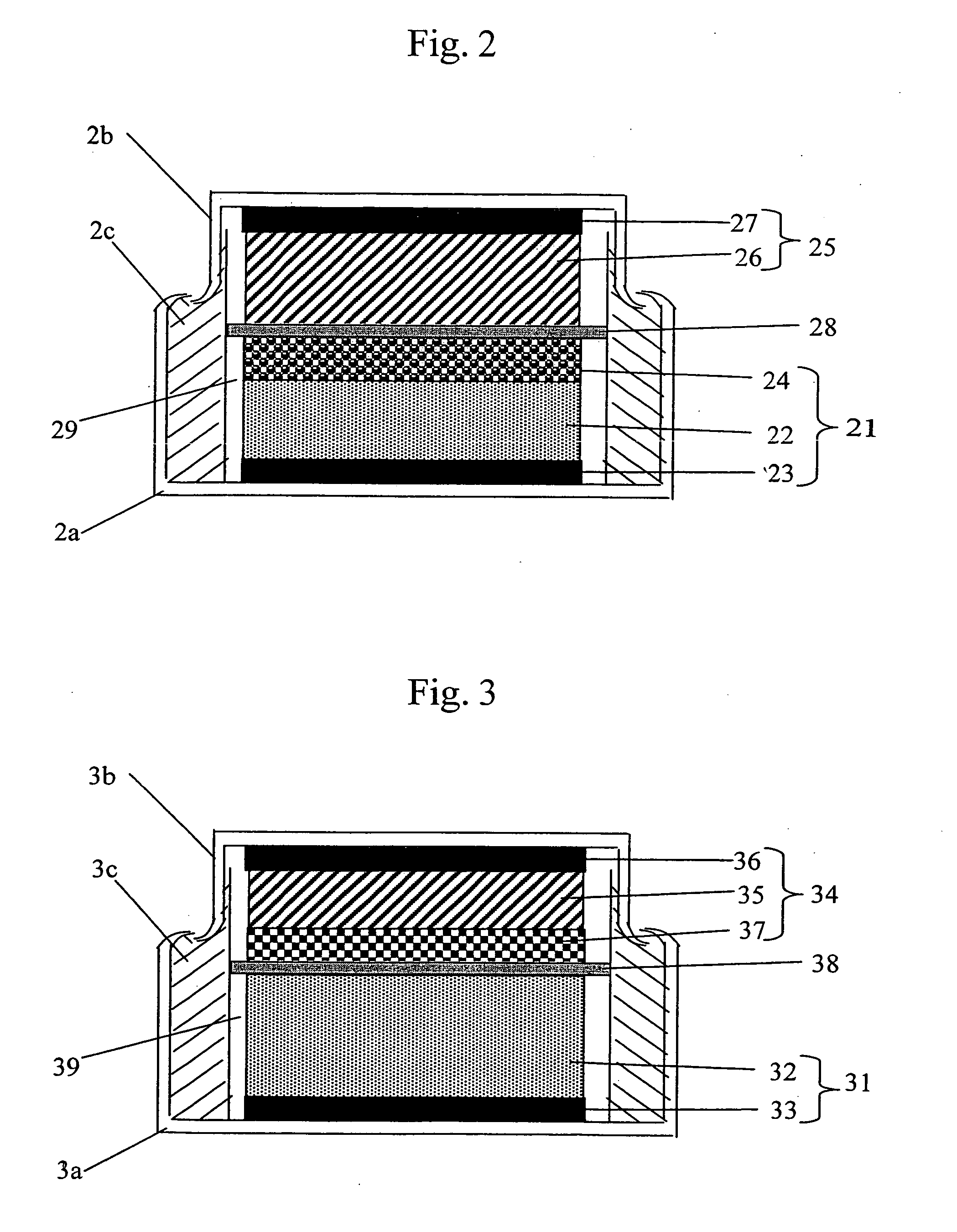
[0059] A coin-type energy device having the configuration shown in FIG. 2 was produced. The positive electrode 22 was produced, in the same way as the positive electrode 72 of Comparative Example 1 except that the weight of the positive electrode mixture was controlled so as to be 12 mg / cm2 in this case, by applying the mixture onto one surface of the positive electrode collector 23 comprising aluminum foil 20 μm in thickness and drying it. Further, activated carbon having a specific surface area of 2,000 m2 / g and carbon black 0.04 μm in average grain diameter having a specific surface area of 40 m2 / g were mixed so that the ratio thereof was 8 to 1 in weight. As the binding agent, solution formed by dissolving polyvinylidene fluoride of 8 wt % in N-methylpyrrolidone beforehand was used. Then the activated carbon, carbon black and polyvinylidene fluoride were put together so that the percentages thereof were 80, 10 and 10% respectively and mixed sufficiently, and the mixture was used...

example 2

[0070] A coin-type energy device having the configuration shown in FIG. 10 was produced. A positive electrode 102 was produced by: forming paste by mixing the mixture of nickel hydroxide powder acting as an active material and cobalt hydroxide acting as an electrically conductive auxiliary agent with the solution produced by dissolving PVA (polyvinyl alcohol) in water; filling foamed metal comprising Ni with the paste; and thereafter drying and pressing it. A layer 103 wherein non-faradaic reaction occurred was formed on the positive electrode 102 by applying thereon slurry in the state of paste produced by mixing the mixture of activated carbon and carbon black acting as an electrically conductive auxiliary agent with the solution produced by dissolving PTFE (polytetrafluoroethylene) in water onto the positive electrode 102 by coating. The product was dried and subjected to roll press, and thus the electrode was produced. The produced electrode was punched into a disk 16 mm in diam...

example 3

[0072] A coin-type energy device having the configuration shown in FIG. 11 was produced. A positive electrode 112 was produced by: coating one surface of a positive electrode collector 113 comprising aluminum foil 1 mm in width and 20 μm in thickness with positive electrode slurry of Comparative Example 1 in such a manner as to form non-coated portions at intervals of 1 mm; and drying them. The weight of the positive electrode mixture was controlled so as to be 25 mg / cm2. Further, activated carbon having a specific surface area of 2,000 m2 / g and carbon black 0.04 μm in average grain diameter having a specific surface area of 40 m2 / g were mixed so that the ratio thereof was 8 to 1 in weight. As the binding agent, solution formed by dissolving polyvinylidene fluoride of 8 wt % in N-methylpyrrolidone beforehand was used. Then the activated carbon, carbon black and polyvinylidene fluoride were put together so that the percentages thereof were 80, 10 and 10% respectively and mixed suffic...


PUM

PropertyMeasurementUnit
temperatureaaaaaaaaaa
diameteraaaaaaaaaa

Abstract

An energy device having high input-output performance, in particular being excellent in low temperature performance. An energy device characterized by storing and discharging electric energy by both a faradaic reaction mechanism wherein mainly the oxidation state of an active material changes and electric charge transfers inside said active material and a non-faradaic reaction mechanism wherein mainly ions are physically absorbed and desorbed on the surface of an active material and resultantly electric charge is accumulated and discharged. Further, output performance at a low temperature is improved by providing an energy device characterized by storing and discharging electric energy by at least two kinds of reaction mechanisms that show low and high reaction rates respectively in faradaic reaction wherein mainly the oxidation state of an active material changes and electric charge transfers to said active material through an electrode interface. Furthermore, an energy device characterized by storing and discharging electric energy by at least two kinds of reaction mechanisms that show low and high reaction rates respectively in faradaic reaction wherein mainly the oxidation state of an active material changes and electric charge transfers to said active material through an electrode interface.

Description

FIELD OF THE INVENTION [0001] The present invention relates to an energy device that stores and discharges electric energy. BACKGROUND OF THE INVENTION [0002] In late years, a power source having higher input-output than ever is longed for as a power source of an electric automobile, a hybrid automobile, an electric tool or the like. Further, a power source that allows rapid charge and discharge and moreover has a higher capacity is longed for. In particular, a power source that is less susceptible to temperature and capable of maintaining high input-output performance even at a low temperature of −20° C. or −30° C. is desired. [0003] Such requirements have hitherto been coped with by: improving the performance of a secondary battery, the reaction mechanism of which is mainly faradaic, such as a lithium secondary battery, a nickel metal hydride battery, a nickel-cadmium battery, a lead acid battery or the like; or using in combination an electric double layer capacitor, the reaction...

Claims


Application Information

Patent Timeline
Patent Type & Authority Applications(United States)
IPC IPC(8): H01G9/00H01G11/06H01G11/08H01G11/10H01G11/22H01G11/24H01G11/30H01G11/38H01G11/42H01G11/46H01G11/58H01G11/62H01G11/78H01G11/86H01M2/02H01M4/13H01M4/32H01M4/36H01M4/38H01M4/44H01M4/56H01M4/62H01M10/00H01M10/05H01M10/052H01M10/0565H01M10/0566H01M10/06H01M10/30H01M10/34H01M10/44H01M14/00
CPCH01G9/155Y02E60/126H01M4/13H01M4/131H01M4/366H01M4/383H01M4/48H01M4/505H01M4/525H01M4/58H01M4/62H01M4/623H01M10/00H01M10/0525H01M10/0565H01M10/06H01M10/30H01M10/345H01M10/44H01M14/00Y02E60/122Y02E60/13Y02T10/7011Y02T10/7016Y02T10/7022Y02E60/124H01M2/0222Y02T10/70Y02E60/10H01M50/109H01G11/06H01G11/46H01G11/56H01G11/30H01G11/50H01G11/58A47C21/048H05B3/20Y02B30/00
Inventor KUMASHIRO, YOSHIAKIARAI, JUICHIKOBAYASHI, MITURUHOSHI, EIJI
Owner HITACHI LTD
Why Eureka
Try Eureka