Electric rotating machine

a rotating machine and electric technology, applied in the direction of magnetic circuit rotating parts, magnetic circuit shape/form/construction, manufacturing stator/rotor bodies, etc., can solve the problems of reversible or irreversible demagnetization, deterioration of characteristics, cooling efficiency, etc., to prevent permanent deterioration of characteristics and improve the effect of characteristics

Active Publication Date: 2005-07-21
MITSUBISHI ELECTRIC CORP
View PDF9 Cites 26 Cited by
  • Summary
  • Abstract
  • Description
  • Claims
  • Application Information

AI Technical Summary

Benefits of technology

[0009] The present invention was made to solve the above-discussed problems and has an object of providing an electric rotating machine in which a permanent magnet mounted on a rotor of the electric rotating machine can be prevented from being rusted and the rotor can be prevented from permanent deterioration of characteristics due to irreversible demagnetization, eventually resulting in improvement of the characteristics.

Problems solved by technology

In the conventional electric rotating machines of mentioned above arrangement, a problem exists in that, in the process of assembling the rotor, the coating comes off at the time of mounting the permanent magnet or due to mixture of foreign matter from outside or heat deterioration, and the permanent magnet rusts eventually resulting in deterioration of characteristics thereof.
In the conventional electric rotating machines mounted with a permanent magnet, because of its arrangement, the permanent magnet may inhibits airflow inside the rotor, making the cooling efficiency down, and furthermore any reversible or irreversible demagnetization may occur due to temperature rise caused by heat generation of the permanent magnet.
Moreover, because of poor heat conduction of the resin coating, in the conventional electric rotating machines, a further problem exists in that cooling efficiency for the permanent magnet is poor, and temperature of the permanent magnet rises due to heat received from the stator coil and eddy current generated in the permanent magnet, occurring the reversible demagnetization, reducing amount of magnetic flux resulting in deterioration of characteristics, which further brings about reduction in magnetic flux density of the permanent magnet due to opposing magnetic field eventually resulting in irreversible demagnetization.

Method used


Image

  • Electric rotating machine
  • Electric rotating machine
  • Electric rotating machine

Examples


embodiment 1

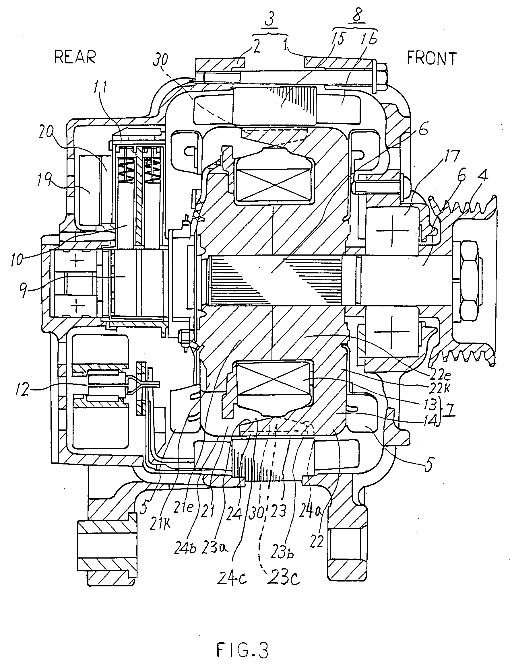
[0024] An electric rotating machine according to Embodiment 1 of the present invention is hereinafter described with reference to FIGS. 1 to 3.

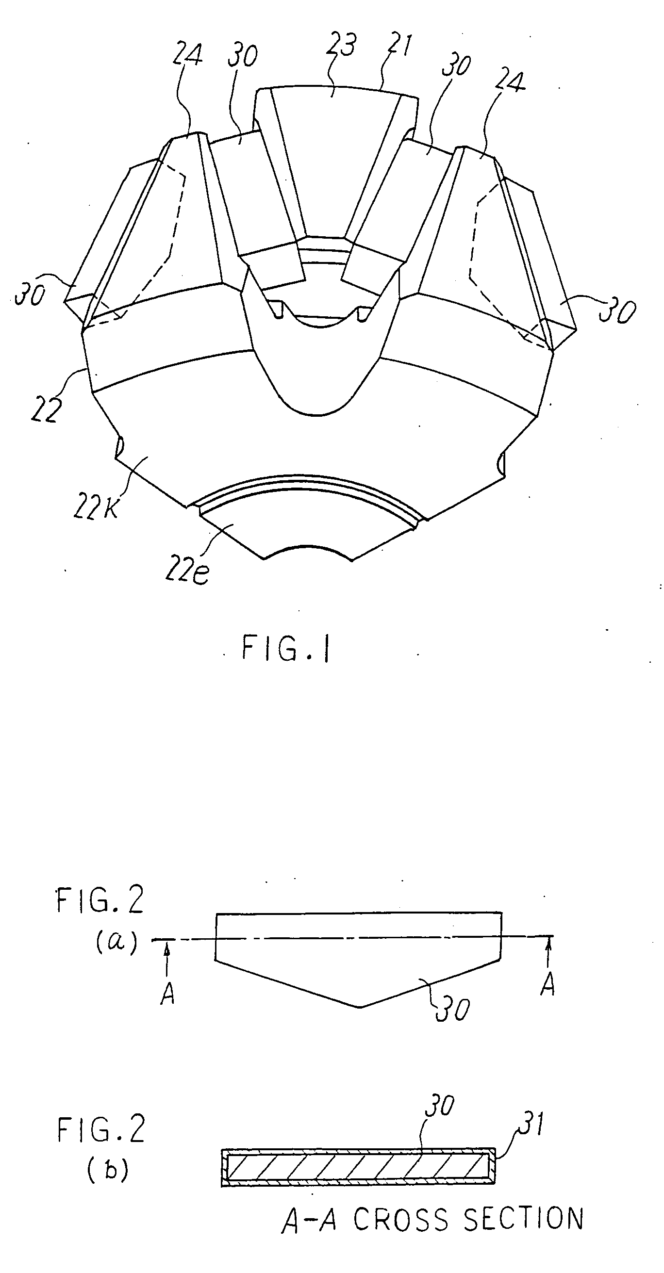
[0025]FIG. 1 is a perspective view showing a rotor incorporated and used in an electric rotating machine. As shown in FIG. 1, this rotor includes: a pole core comprised of a first pole core 21 and a second pole core 22 respectively having claw-shaped magnetic poles 23, 24 protruding like an alternate engagement with each other; and a permanent magnet 30 disposed between the claw-shaped magnetic poles 23, 24 on both sides thereof. The permanent magnet 30 acts to reduce leakage of magnetic flux between the claw-shaped magnetic poles 23, 24 adjacent to each other. The pole core is formed covering with a rotor coil as described later. The rotor is comprised of the pole core and a rotor winding described later.

[0026] FIGS. 2(a) and (b) are a side view and a sectional view of the permanent magnet 30 according to Embodiment 1 of the invention. FIG...

embodiment 2

[0041] An example of coating the permanent magnet 30 forming the rotor is coated with a single coating layer 31 is shown in the foregoing Embodiment 1. Now, as shown in a side view of FIG. 4 (a) and a sectional view of FIG. 4(b) taken along the line B-B of FIG., 4(a), an example of coating with the anticorrosive material forming a multi-layer structure (two-layer structure in the example of FIG. 4) is described in this Embodiment 2.

[0042] The multi-layer structure is formed by nickel plating and zinciferous inorganic material coating, and the nickel plating forms either a nickel plating layer (lower layer) 31 or a coating layer (upper layer) 32. Otherwise, the multi-layer structure is formed by aluminum plating and zinc plating, and the aluminum plating forms either an aluminum plating layer (lower layer) 31 or a coating layer (upper layer) 32. In other words, a two-layer structure is established irrespective of coating order of the nickel plating layer and zinciferous inorganic ma...

embodiment 3

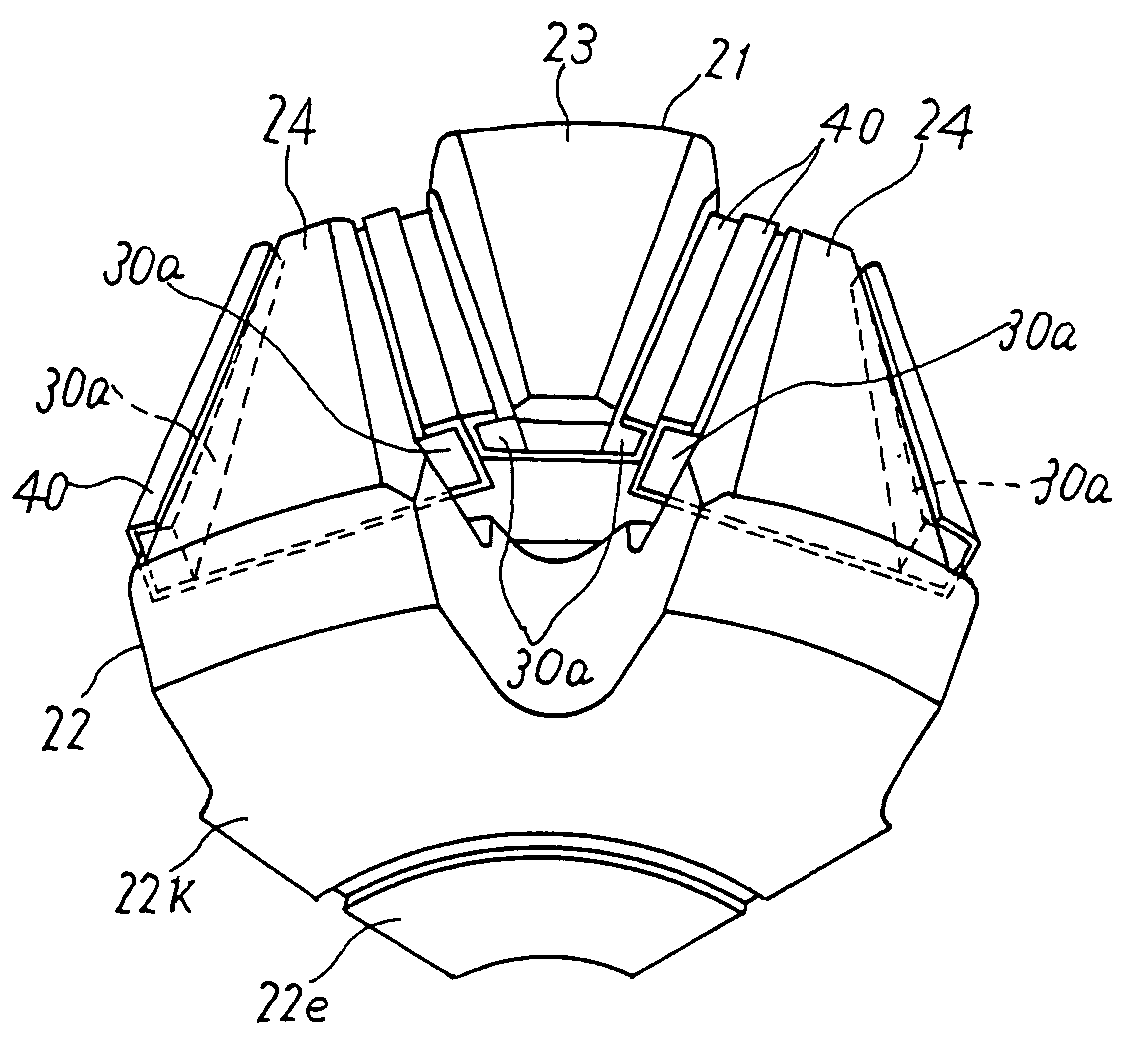
[0047] An example of disposing each one permanent magnet 30 between the claw-shaped magnetic poles 23, 24 is shown in the foregoing Embodiment 1 and Embodiment 2. Now in this Embodiment 3, an example of disposing two permanent magnets 30a respectively on two sides of one claw-shaped magnetic pole 23 (24) (in other words, two permanent magnets 30a between the claw-shaped magnetic poles 23, 24) is described. As shown in FIG. 5(a) being a perspective view of an essential part of the rotor, FIG. 5(b) being an exploded view of the essential part and FIG. 5(c) being a developed view of a holding member for holding the permanent magnets 30a, the permanent magnets 30a are disposed on each side of each claw-shaped magnetic pole 23, 24, and the permanent magnets 30a are held on the claw-shaped magnetic pole 23 (24) by means of a metallic holding member 40.

[0048] As shown in FIGS. 5(a), (b) and (c), the holding member 30 holds the two permanent magnets 30a disposed on both sides of the claw-s...


PUM

PropertyMeasurementUnit
thicknessaaaaaaaaaa
electrical angleaaaaaaaaaa
magnetic fluxaaaaaaaaaa

Abstract

Claw-shaped magnetic poles are alternately disposed along the rotation plane of a rotor of an electric rotating machine, and a permanent magnet is disposed between the claw-shaped magnetic poles. Surface of the permanent magnet is coated with a coating layer. The coating layer is composed of a anticorrosive material performing sacrificial anticorrosion (metal flake in a coating film rusts prior to a matrix resulting in protection of the matrix) such as inorganic material containing zinc and a film of the anticorrosive material is formed by spraying. Ionization tendency of zinc is larger than that of iron composing the permanent magnet, and the permanent magnet is difficult to be rusted owing to the sacrificial anticorrosion. Consequently, anticorrosion of the permanent magnet disposed between the claw-shaped magnetic poles is improved.

Description

BACKGROUND OF THE INVENTION [0001] 1. Field of the Invention [0002] The present invention relates to an electric rotating machine. [0003] 2. Description of the Prior Art [0004] In the conventionally electric rotating machines having a field rotor in which a field winding is wound round on a pole core, it has been a known technique that a permanent magnet is mounted between claw-shaped magnetic poles adjacent to each other in circumferential direction of the pole core (as disclosed in, for example, the Specification of Japanese Patent No. 2548882). [0005] The permanent magnet not only reduces leakage flux between the claw-shaped magnetic poles but also increases effective magnetic flux that contributes to power generation by interlinkage of the magnetic flux, thus improving power output of the electric rotating machine. The rotor is arranged to have a ventilation space for separating the permanent magnet and the field winding from each other with a predetermined radial distance, and ...

Claims


Application Information

Patent Timeline
Patent Type & Authority Applications(United States)
IPC IPC(8): H02K19/22H02K1/04H02K1/22H02K15/03H02K21/04
CPCH02K21/044H02K1/04
Inventor IMAI, DAISUKEASAO, YOSHIHITOFUJITA, MASAHIKO
Owner MITSUBISHI ELECTRIC CORP
Why Eureka
Try Eureka