Method and apparatus for multi-mode spectral imaging

a multi-mode, spectral imaging technology, applied in the direction of fluorescence/phosphorescence, optical radiation measurement, instruments, etc., can solve the problems of low transmission efficiency, significant light loss, and inability to provide two-dimensional spatial maps of the spectra emanating from an obj

Active Publication Date: 2005-07-21
TELEDYNE DIGITAL IMAGING US INC
View PDF9 Cites 33 Cited by
  • Summary
  • Abstract
  • Description
  • Claims
  • Application Information

AI Technical Summary

Benefits of technology

[0020] One embodiment employs a grating to disperse the light and a piezoelectric crystal-based stage for spatial scanning of the object. The grating subassembly is preferably removable, allowing full-field imaging, or replaceable by an optical beamsplitting module, thereby allowing simultaneous acquisition of multiple component images having different optical properties. At least one aperture illuminates a portion of the object being evaluated (the same portion that is being imaged), allowing for confocal operation and minimization of photobleaching artifacts and phototoxicity.

Problems solved by technology

While standard spectrometers are excellent devices for determining the spectral composition of all the light emanating from an object, they are typically unable to provide two dimensional spatial maps of the spectra emanating from an object.
For example, these systems are polarization-sensitive and, as a result, they have low transmission efficiency, resulting in significant light loss.
This is the result of the physics of the LCTF and a practical limitation imposed by the significant light loss.
Therefore, high-spectral resolution (less than 2 nm) imaging is rarely possible with these systems.
However, there are certain limitations imposed by the physical geometry of these systems.
In addition, in both cases, the system field of view is restricted.
For example, with regard to the FTS system, the length of the system, combined with the small size of the mirrors, restricts the field of view because optical rays will not propagate through the system for large angles.
Therefore, the number of points on an object which can be acquired is limited.
Another problem arises with respect to image registration.
Problems associated with scanning, such as mirror jitter, uneven scanning, or beam-walking, create registration problems between the images in the different spectral bands.
With regard to the FPS system, it is also limited to a small field of view because of two main effects.
Consequently, as the light undergoes multiple reflections, it will walk along the mirrors and eventually leak out of the cavity.
Another problem with the FPS configuration has to do with spectral bandpass variation with field.
Typically spectral scanning systems suffer from the fact that their inherent design does not allow for confocal imaging of the object.
Spectral scanning systems have no spatial scanning attribute, making confocal microscopy impossible.
In addition, all spectral scanning systems have a fundamental flaw when used in low light applications such as fluorescence microscopy.
These applications suffer from a phenomenon called photobleaching, where the fluorescence of an object decreases with the length of the exposure, and phototoxicity, where the light that is used to illuminate the object is toxic to the object.
This change in intensity is not something that can easily be corrected after acquisition of the images.
If toxicity becomes an issue, then the object's characteristics will change over time as the object becomes damaged.
This effect cannot be corrected for post acquisition.
However, prism-based systems have the significant disadvantage of producing non-linear dispersion, requiring data correction via interpolation for proper visualization and processing.
The symmetry of the design minimizes optical aberration's; however, to obtain a reasonable field-of-view, the optical train tends to be long, preventing the development of a compact system.
This causes a significant problem in fluorescence microscopy applications that are often, by their nature, highly polarization-dependent processes.
These approaches are generally very slow and do not have the necessary accuracy or temporal resolution for live-cell microscopy imaging applications.
Finally, all of these high-spectral resolution imaging systems are only capable of providing high-spectral resolution with low temporal resolution.
While different methods may be used to achieve imaging spectrometry, the prior art is generally not capable of providing the required performance within a compact, modular, flexible and fast system.
The prior art also fails to disclose providing multiple imaging modalities within a single system.

Method used


Image

  • Method and apparatus for multi-mode spectral imaging
  • Method and apparatus for multi-mode spectral imaging
  • Method and apparatus for multi-mode spectral imaging

Examples


Embodiment Construction

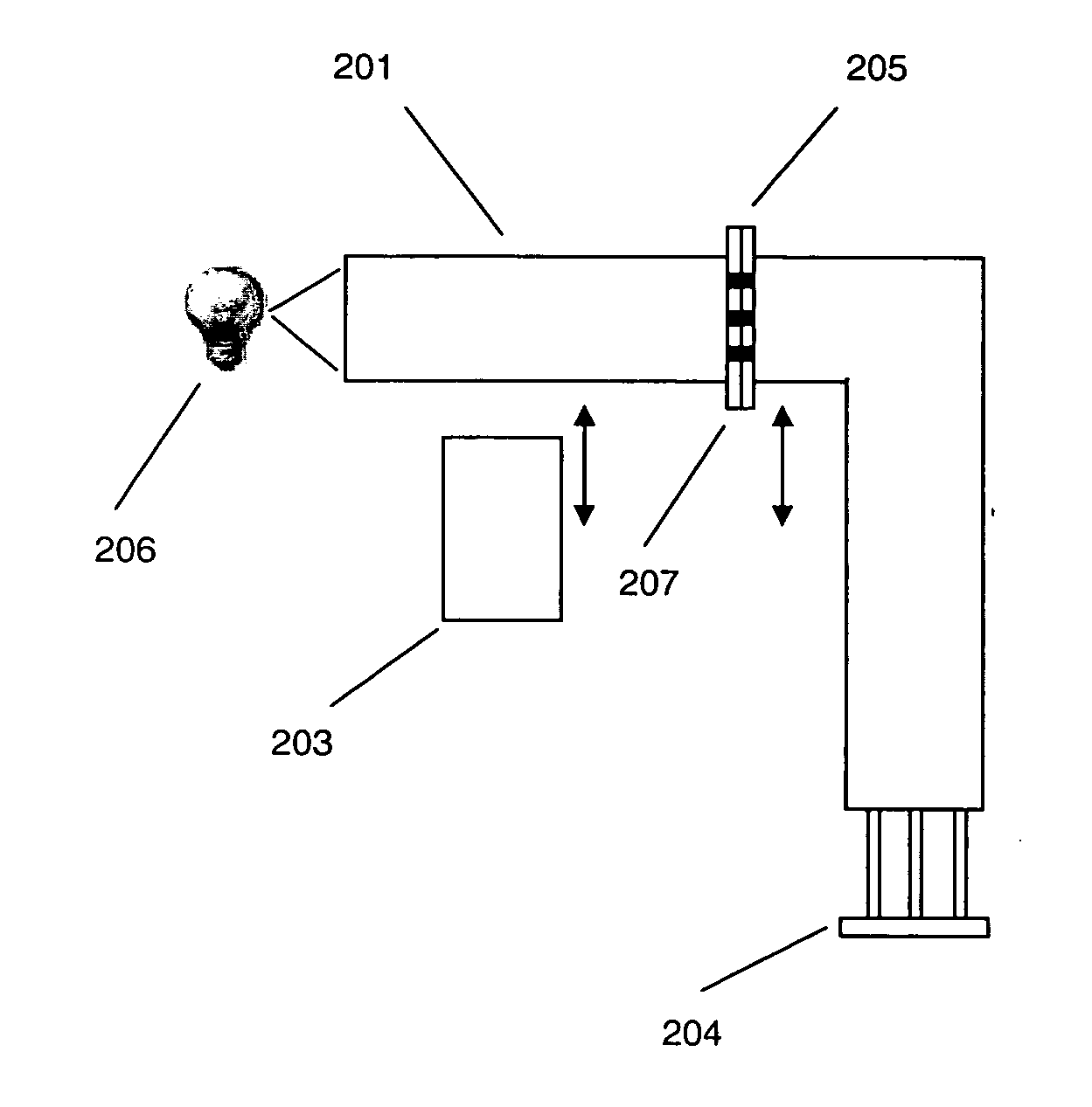
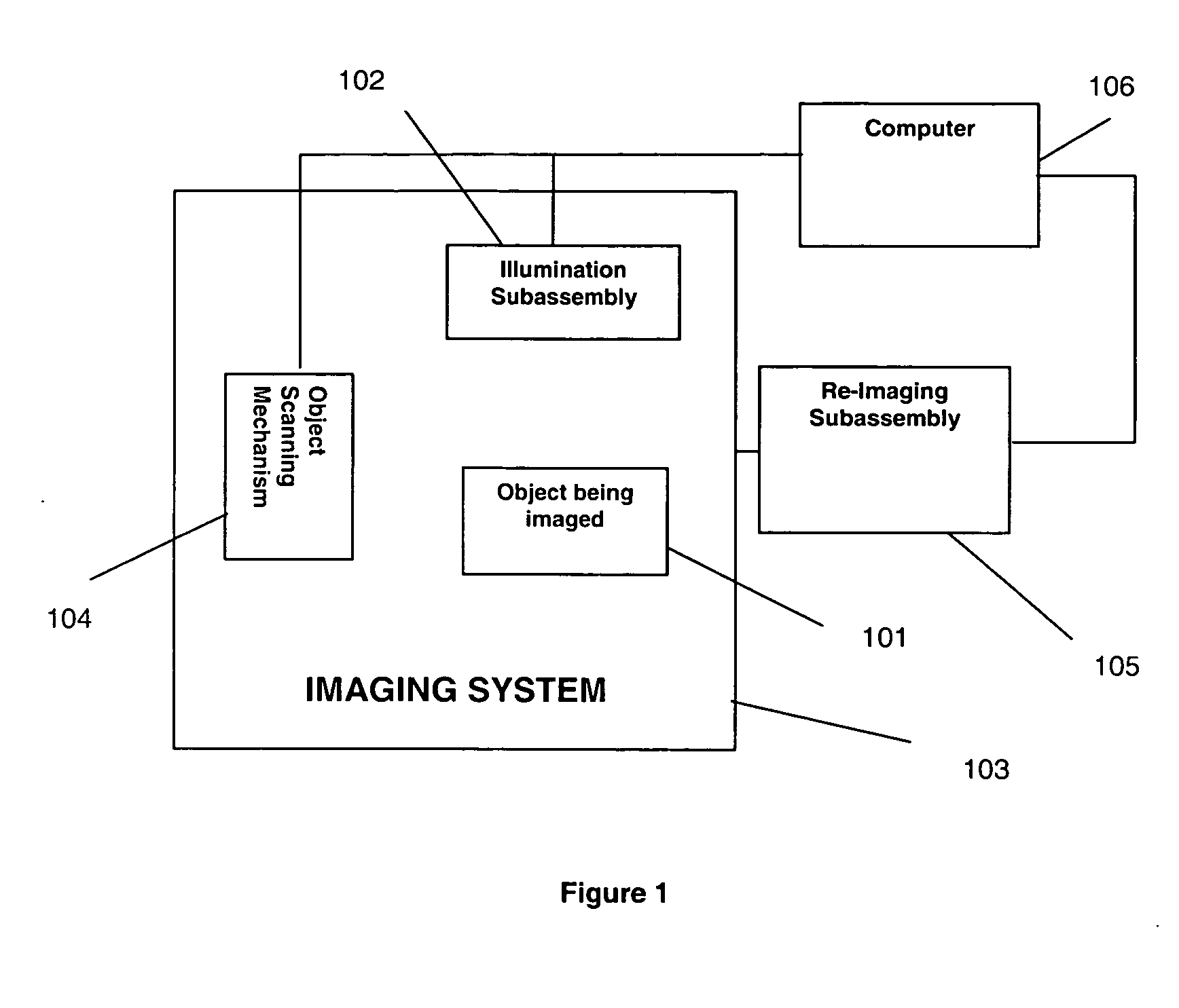
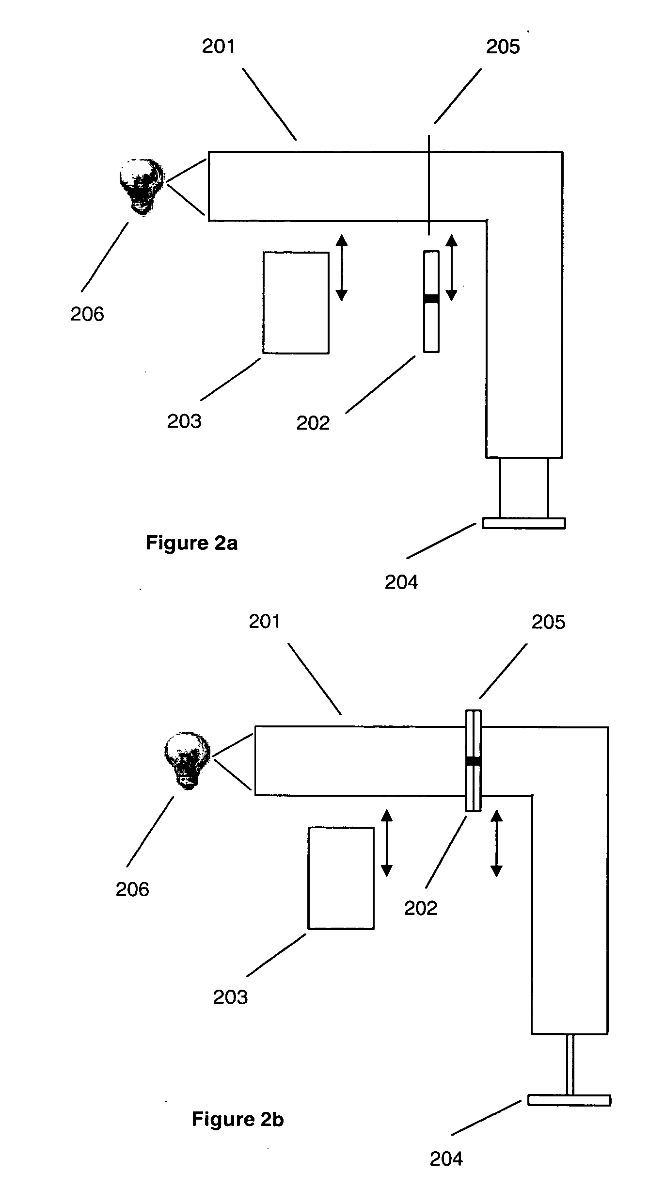
[0045] The present invention is a multi-mode spectral imaging method and apparatus for acquiring multi-dimensional images. The present invention allows for the creation of at least one image data cube corresponding to the same two-dimensional image at more than one wavelength, polarization or intensity. This data cube, in one embodiment, may be produced in two modes. In mode #1, multiple high-spatial resolution images are acquired simultaneously at either a small number of wavelengths (low spectral resolution), a small number of polarization states, or a small number of intensities, thereby achieving high temporal resolution images. In mode #2, the object is scanned in time to produce high-spatial resolution images, with high spectral resolution. However, due to the scanning nature of mode #2, the temporal resolution is limited by the scan rate. When critical illumination conditions are satisfied, mode #2 can be operated with the additional feature of confocal imaging. All imaging m...


PUM

PropertyMeasurementUnit
fluorescenceaaaaaaaaaa
areas of illuminationaaaaaaaaaa
optical statesaaaaaaaaaa

Abstract

A method and apparatus is disclosed for multi-mode spectral imaging. In one embodiment, the present invention comprises the steps of illuminating an object with a modified illumination profile, producing a reflected, transmitted or fluorescence image of the illuminated object, scanning the object, and re-imaging the reflected, transmitted or fluorescence light after modifying the light's optical state. The present invention preferably works in conjunction with other imaging systems to provide both high-spectral resolution images with lower temporal resolution and multiple image acquisition with high temporal resolution.

Description

REFERENCE TO RELATED DOCUMENTS [0001] This invention claims priority to, and the benefit of, U.S. Provisional Patent Application Ser. No. 60 / 537,839, entitled “Slit-Scanning Confocal Imaging Spectrometer”, filed Jan. 21, 2004, the entire contents of which are hereby incorporated by reference.TECHNICAL FIELD OF INVENTION [0002] This invention applies broadly to the area of spectroscopic systems and imaging spectrometry. More specifically, the present invention comprises a multi-mode spectral imaging method and apparatus allowing for the spectroscopic evaluation of an object while maintaining the spatial integrity of the image being evaluated. This method, in one embodiment, provides for the acquisition of a series of spectrally-discrete, two-dimensional images in conjunction with at least one other optical system such as a microscope or a fundus camera. The resulting data cube provides high-resolution spectral and spatial information at each pixel in the image. The confocal nature of...

Claims


Application Information

Patent Timeline
Patent Type & Authority Applications(United States)
IPC IPC(8): G01J3/04G01J3/10G01J3/28G01J3/30G01J3/36G01N21/64G02B21/26
CPCG01J3/0202G02B21/26G01J3/0235G01J3/0237G01J3/024G01J3/0291G01J3/04G01J3/10G01J3/2823G01J3/2889G01J3/36G01N21/6458G01N2021/6423G01N2021/6463G01N2021/6471G01N2201/024G01N2201/10G01N2201/103G01J3/0229
Inventor HOPKINS, MARK F.SABHARWAL, YASHVINDERVERNOLD, CYNTHIA
Owner TELEDYNE DIGITAL IMAGING US INC
Why Eureka
Try Eureka