Hydride-based fuel cell designed for the elimination of hydrogen formed therein

a fuel cell and hydrogen-based technology, applied in the direction of fuel cells, fuel cell auxilaries, electrical devices, etc., can solve the problems of hydride-based fuel, unfavorable gas (hydrogen) evolution, storage and transportation, etc., and achieve the effect of enhancing the stability toward chemicals

Inactive Publication Date: 2005-07-21
MORE ENERGY
View PDF60 Cites 11 Cited by
  • Summary
  • Abstract
  • Description
  • Claims
  • Application Information

AI Technical Summary

Benefits of technology

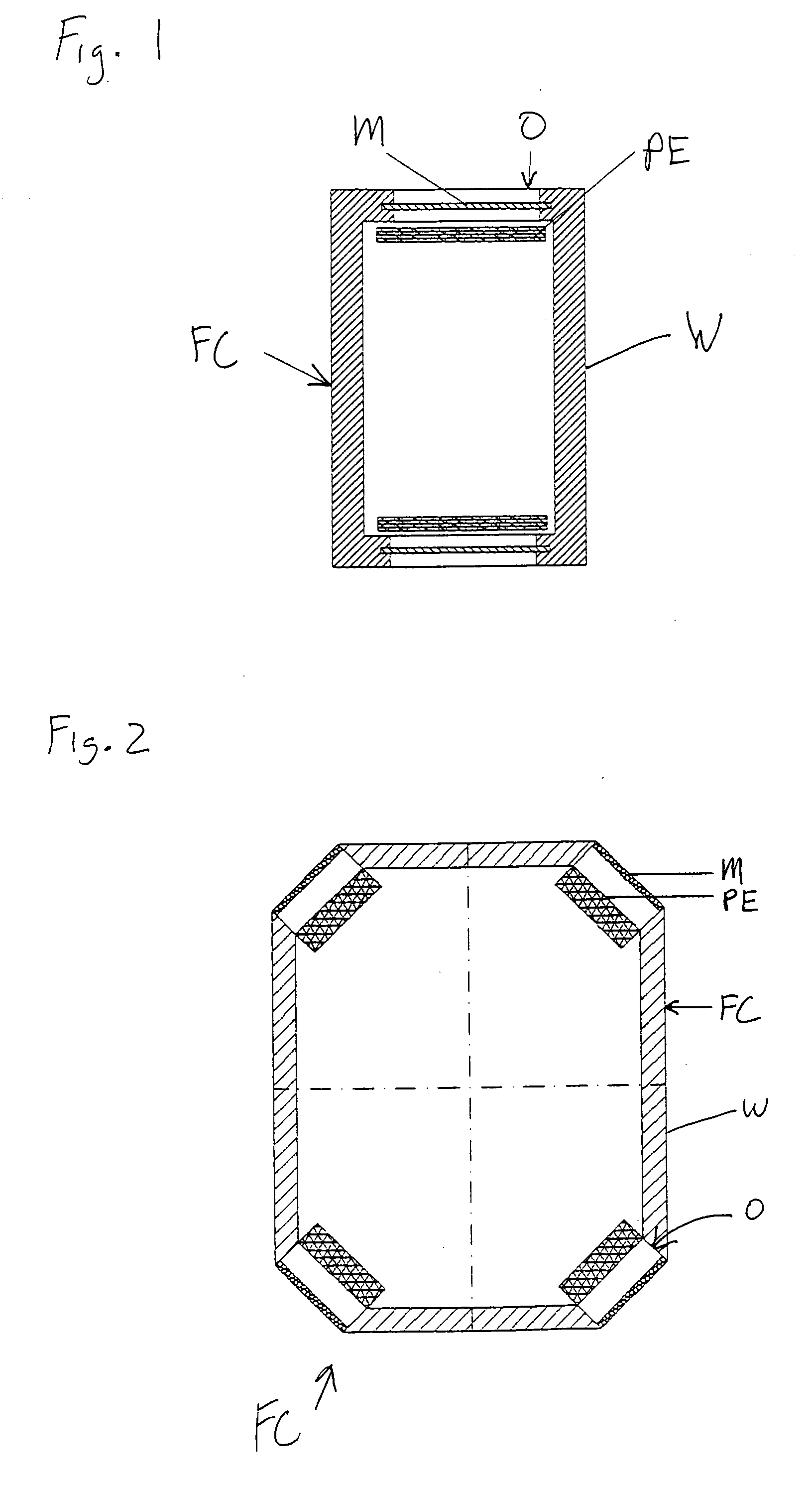
[0083] As indicated above, it will usually be desirable to physically separate the materials which are capable of absorbing, adsorbing and / or undergoing a chemical reaction with molecular hydrogen from the solid and liquid components and decomposition and reaction products of the hydride-based fuel while still allowing sufficient access of hydrogen to these materials. A preferred way of accomplishing this according to the present invention is to enclose these materials inside the fuel cell in one or more structures (e.g., containers) which are composed, at least in part, of a material which is liquid- (and solid-) impervious and pervious to hydrogen. The remainder of the structures, if any, should comprise materials which are impervious to both liquid and gaseous substances. Of course, the material or materials of which the enclosing structures are composed should be substantially inert toward and resistant to the hydride-based fuel and its decomposition and reaction products, the electrolyte, as well as the substances contained inside the structures, e.g., hydrogen-reactive materials and corresponding catalysts (as well as solvents, reaction products, etc.). At least the hydrogen-pervious parts of the structure(s) may often comprise materials similar to (or identical with) those discussed above as materials for the membranes, in particular, the porous membranes. To enhance the stability toward the chemicals inside and outside the structure(s), the inner and / or outer surfaces of the structure(s) may be coated with suitable materials which will not adversely affect the desired hydrogen-permeability to any significant extent (for example with the coating materials discussed above).

Problems solved by technology

Conventional fuels such as hydrogen and methanol pose several storage and transportation problems, in particular, for portable fuel cells (e.g., for use with portable electric and electronic devices such as laptops, cell phones, and the like).
However, hydride-based fuels also pose problems, for example, undesired gas (hydrogen) evolution, which apparently is of particular concern in fuel cells which are to operate in a sealed condition.
The formation of hydrogen gas inside the fuel cell through, e.g., the above-described reactions, results in an increase in the pressure inside the fuel cell and thereby may cause substantial problems such as, e.g., destruction of the anode, changes in the electrical properties of the fuel cell and in some cases even an explosion of the fuel chamber.
However, when these known membranes are used with a fuel cell which contains, e.g., a borohydride-based fuel, various technical problems are encountered.
This aerosol may damage the membrane both physically and by chemical attack.
All these effects adversely affect the gas permeability of a membrane.

Method used


Image

  • Hydride-based fuel cell designed for the elimination of hydrogen formed therein
  • Hydride-based fuel cell designed for the elimination of hydrogen formed therein
  • Hydride-based fuel cell designed for the elimination of hydrogen formed therein

Examples


example 1

Procedure for Coating a PTFE Membrane with a Hydrophobic Material

[0121] The membrane to be coated is first cleaned by dipping it into ethanol and thereafter into acetone, each for a few seconds. The membrane is then left to dry in air for at least about 20 minutes, whereafter it is transferred into a vacuum oven and dried for about 30 minutes at about 70° C. The thus cleaned and dried membrane is dipped into a solution of the coating material (e.g., FluoroPel® PFC 601A, a 1% fluoropolymer solution in 3M HFE 7100 fluorosolvent (b.p. 61° C.)) for about 10-15 seconds. The thus coated membrane is left to dry in air for about 30 minutes and then vacuum-dried at 90° C. for about 2 hours.

example 2

Procedure for Coating a Membrane with an Oxide Surface with a Hydrophobic Material

[0122] The membrane with an oxide surface (e.g., comprising glass, metal etc.) is treated in the same manner as described in Example 1, but using FluoroSyl® FSM660 (a fluoroalkyl monosilane in a high boiling fluorinated surface providing low surface energy to oxide surfaces and a good adhesion for fluoropolymers) instead of FluoroPel® PFC 601A.

example 3

[0123] Membranes of Activated Carbon and PTFE

ActivatedMembraneCarbonPTFEThicknessNo.(wt.-%)(wt.-%)(μm)185154502851522037030400470302705505040065050200

[0124] The above membranes are made by subjecting powders of activated carbon (Pica Ltd., USA) and PTFE to high-speed milling and rolling the resultant dough or paste to the desired thickness. By compressing the membranes, a dense material with nm sized pores may be produced.

[0125] Membranes similar to the above membranes but having a thickness of 200 μm and 100 μm, respectively, are included in a bi-layer configuration by combining them with a PTFE membrane (100% PTFE, thickness 100 μm), to form bi-layer membranes having total thicknesses of 300 μm and 200 μm, respectively.

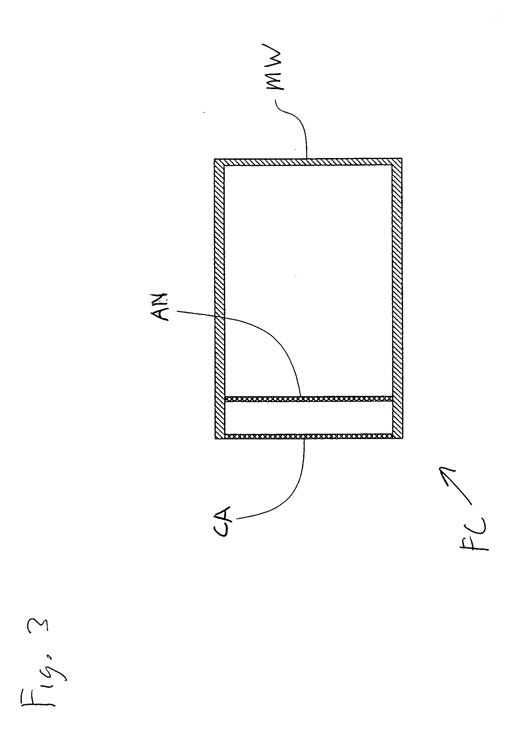
[0126] By way of one non-limiting example, FIG. 1 shows a fuel cell FC for use with a hydride-based fuel. The fuel cell FC is designed for being sealed in a liquid-tight manner when in operation. The fuel cell FC may include one or more openings, e.g., two openi...


PUM

PropertyMeasurementUnit
diametersaaaaaaaaaa
thicknessaaaaaaaaaa
thicknessaaaaaaaaaa

Abstract

A fuel cell for use with a hydride-based fuel, which fuel cell is designed for being sealed in a liquid-tight manner when in operation. The fuel cell comprises means for eliminating hydrogen formed inside the fuel cell. This abstract is neither intended to define the invention disclosed in this specification nor intended to limit the scope of the invention in any way.

Description

BACKGROUND OF THE INVENTION [0001] 1. Field of the Invention [0002] The present invention relates to a fuel cell for use with a hydride-based fuel which comprises means for the elimination of hydrogen gas formed therein. [0003] 2. Discussion of Background Information [0004] Fuel cells are electrochemical power sources wherein electrocatalytic oxidation of a fuel at an anode and electrocatalytic reduction of an oxidant (often molecular oxygen) at a cathode take place simultaneously. Conventional fuels such as hydrogen and methanol pose several storage and transportation problems, in particular, for portable fuel cells (e.g., for use with portable electric and electronic devices such as laptops, cell phones, and the like). Borohydride (and other metal hydride) based fuels, on the other hand, are of particular interest for portable fuel cells due, in particular, to their very high specific energy capacity. Examples of corresponding fuels are disclosed, e.g., in U.S. 20010045364 A1, U.S...

Claims


Application Information

Patent Timeline
Patent Type & Authority Applications(United States)
IPC IPC(8): H01M2/08H01M2/14H01M4/92H01M8/00H01M8/02H01M8/06H01M8/10
CPCH01M8/0271H01M8/0282Y02E60/50H01M8/065H01M8/0687H01M8/0284
Inventor FINKELSHTAIN, GENNADISILBERMAN, ALEXANDERESTRIN, MARKDERZY, IGORSANCHEZ-CORTEZON, EMILIOMINERS, JAMES H.GOUEREC, PASCAL
Owner MORE ENERGY
Why Eureka
Try Eureka