Supercharge Your Innovation With Domain-Expert AI Agents!

Soldering method of nonaqueous-electrolyte secondary-battery

a nonaqueous, electrolyte technology, applied in the direction of secondary cells, cell components, non-aqueous electrolyte cells, etc., can solve the problems of degradation or damage of batteries, difficult to secure a space for inserting soldering irons, etc., to prevent the damage of substrates, and prevent the degradation of battery characteristics

Inactive Publication Date: 2005-08-04
SEIKO INSTR INC
View PDF2 Cites 11 Cited by
  • Summary
  • Abstract
  • Description
  • Claims
  • Application Information

AI Technical Summary

Benefits of technology

The invention is a method for reflow soldering nonaqueous-electrolyte secondary batteries that prevents damage to the battery and degradation of its performance during the heat treatment process. The method involves discharging the battery and heating it while applying a voltage to it. The discharge voltage value at the end of the discharging process is higher than the inflectional value on the discharge curve of the battery. This prevents damage to the substrate and ensures that the battery performs its duties effectively. The method also limits the amount of damage to the battery's capacity and ensures that it is not more than 80% or 20% of its total discharge capacity. Overall, this method improves the battery's performance and prevents it from becoming a liability during the reflow soldering process.

Problems solved by technology

However, since the number of electronic components mounted on a fixed area in the printed circuit board has been required to be increased with progress of miniaturization of devices or improvement in device performance, it has been difficult to secure a space for inserting the soldering iron.
The conventional coin-type (button-type) nonaqueous-electrolyte secondary-battery is not designed to withstand a high temperature at which the reflow soldering can be performed, and degradation or damage occurs in the battery due to the high temperature.
However, the conventional inventions show degradation of battery characteristics such as decrease in battery capacity or increase in internal resistance of the battery due to heat treatment during the reflow soldering.

Method used


Image

  • Soldering method of nonaqueous-electrolyte secondary-battery
  • Soldering method of nonaqueous-electrolyte secondary-battery

Examples


first embodiment

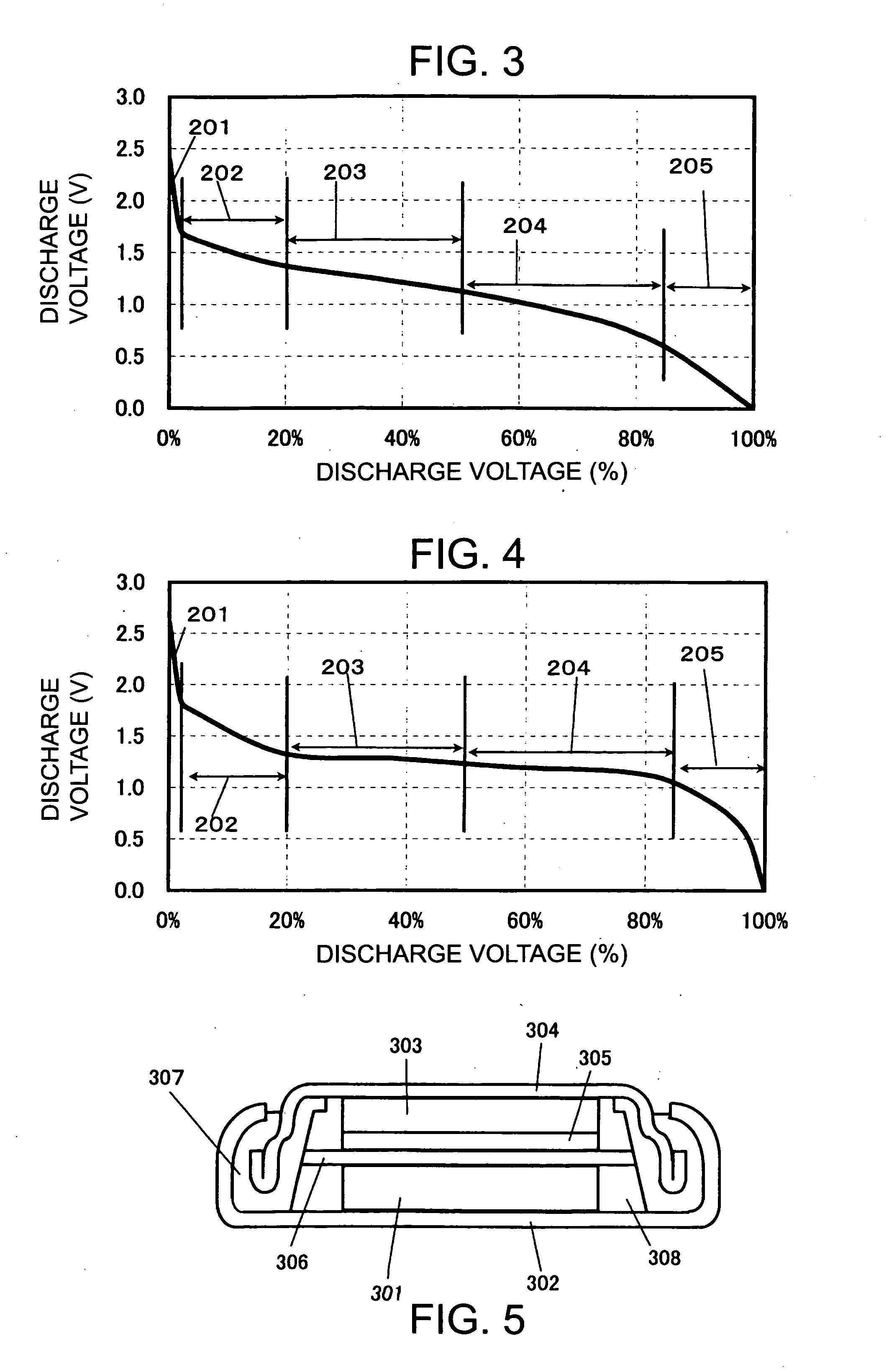
[0047] This embodiment is a case where Li4Ti5O12 is used as the active material for cathode and SiO as the active material for anode. A cathode, an anode, and an electrolyte prepared in a following way were used. The dimension of the battery was 4.8 mm in outer diameter and 1.4 mm in thickness. A cross section view of the battery is shown in FIG. 5.

[0048] In the first embodiment, the cathode was prepared in the following manner. Commercial Li4Ti5O12 was crushed, and then mixed with graphite as a conductive agent and polyacrylic acid as a binder in a weight ratio of Li4Ti5O12 / graphite / polyacrylic acid=85 / 13 / 2, thereby a cathode mixture was formed, and then the cathode mixture of 4 mg is pressed and molded into a pellet 2.4 mm in diameter at 2 ton / cm2. Then, the cathode pellet 301 obtained in this way was adhered to a cathode case 302 using a conductive resin adhesive containing carbon and integrated together (cathode unitization), and then subjected to drying by heating under reduce...

second embodiment

[0056] In this embodiment, Nb2O5 was used as the active material for the cathode, and as other components, the same components as the first embodiment were used, and a battery was produced similarly to the first embodiment.

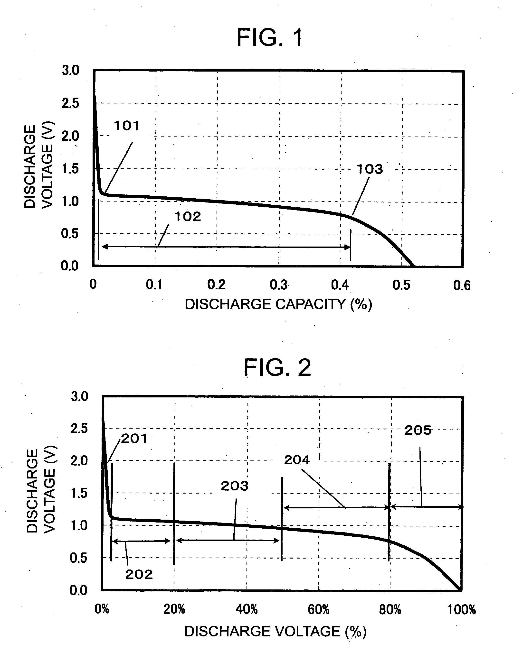
[0057] The initial discharge curve of the battery was made in the same way as the first example. A graph as shown in FIG. 3 is a graph by plotting the discharge voltage (V) in ordinate and the discharge ratio (%) to the total discharge capacity of the secondary battery in abscissa. In FIG. 3, a region to the minimum value in the discharge curve was assumed to be a discharge region A201. Furthermore, the voltage plateau region 102 indicating the cell reaction was subdivided into three, and it was assumed that a region where discharge was performed beyond the discharge region A 201 in FIG. 2 to the discharge capacity of 20% was a discharge region B(1) 202, a region from the discharge capacity of 20% to 50% was a discharge region B(2) 203, and a region from the disc...

third embodiment

[0060] This embodiment employs Nb2O5 as the active material for cathode and a Li—Al alloy as the active material for anode. The cathode, in which Nb2O5 was used as the active material, was prepared according to the same procedure as the first embodiment.

[0061] For the anode, an Al sheet 2.9 mm in diameter and 0.10 mm in thickness was welded to an anode can by an ultrasonic welding. The anode can was dried and then pressed with a Li sheet 2 mm in diameter and 0.2 mm in thickness, thereby a Li—Al alloy anode was prepared.

[0062] For other components, the same components as the first embodiment were used, and a battery was produced in the same way as the first embodiment.

[0063] The discharge curve of the battery is shown in FIG. 4. The battery was subjected to the heating in the reflow oven at the maximum temperature of 240° C., and evaluated similarly to the first embodiment. However, in the measurement of the capacity, the battery was charged for 48 hours at the charging voltage of...


PUM

PropertyMeasurementUnit
melting pointaaaaaaaaaa
temperatureaaaaaaaaaa
outer diameteraaaaaaaaaa

Abstract

In a nonaqueous-electrolyte secondary-battery that is soldered to a circuit board by a reflow soldering process, there has been a problem that when a secondary battery that requires discharging a after assembling the battery that requires discharging after assembling the battery is subjected to reflow, battery characteristics degrade due to heat treatment. Discharge voltage at the end of the discharging is made to be higher than a discharge voltage value that is an inflectional value at the end of a voltage plateau region indicating a cell reaction in a discharge curve (discharge capacity in abscissa and discharge voltage in ordinate) of initial discharge, thereby degradation of the battery characteristics due to the reflow hear treatment can be suppressed.

Description

BACKGROUND OF THE INVENTION [0001] 1. Field of the Invention [0002] The present invention relates to a soldering method of a nonaqueous-electrolyte secondary-battery, particularly relates to reflow soldering. [0003] 2. Background Art [0004] A coin-type (button-type) nonaqueous-electrolyte secondary-battery expands in application as a power supply for backup of devices because of its characteristics such as high energy density and lightweight. [0005] When a secondary battery is used for a memory backup supply, in many cases, the battery is welded with a terminal for soldering, and then soldered on a printed circuit board together with a memory element. The soldering on the printed circuit board has been carried out using a soldering iron. However, since the number of electronic components mounted on a fixed area in the printed circuit board has been required to be increased with progress of miniaturization of devices or improvement in device performance, it has been difficult to secu...

Claims


Application Information

Patent Timeline
Patent Type & Authority Applications(United States)
IPC IPC(8): B23K20/10H05K3/34B23K31/02H01M6/16H01M10/05H01M10/44H01M50/186H01M50/193
CPCB23K20/10H01M2/0222H01M2/08H01M10/0525H01M10/44H01M10/448Y10T29/49108H01M2300/0037H05K3/341Y10T29/49112Y10T29/49115Y10T29/4911Y10T29/49114H01M10/5006H01M10/615Y02E60/10H01M50/109H01M50/193H01M50/186
Inventor KANNO, YOSHIMIEGASHIRA, AGASAISHIKAWA, HIROAKIWATANABE, SHUNJISAKAI, TSUGIO
Owner SEIKO INSTR INC
Features
  • R&D
  • Intellectual Property
  • Life Sciences
  • Materials
  • Tech Scout
  • Unparalleled Data Quality
  • Higher Quality Content
  • 60% Fewer Hallucinations
Learn More