Electronic devices and its production methods

Active Publication Date: 2005-08-04
SHINKO ELECTRIC IND CO LTD
View PDF27 Cites 232 Cited by
  • Summary
  • Abstract
  • Description
  • Claims
  • Application Information

AI Technical Summary

Benefits of technology

[0012] An object of the present invention is to provide an electronic device for mounting an MEMS element or other functional elements, which i

Problems solved by technology

MEMS elements are extremely small in size, yet exhibit complicated and sophisticated functions.
With this method of securing the lid, however, the following numerous problems remain to be solved.
Deterioration of the element due to heat and adverse effects on the element characteristics due to the decomposed gas derived from the adhesive at the time of heating occur.
Such adverse effects due to heating are important problems in electronic devices having mounted thereon functional elements prov

Method used


Image

  • Electronic devices and its production methods
  • Electronic devices and its production methods
  • Electronic devices and its production methods

Examples


example 1

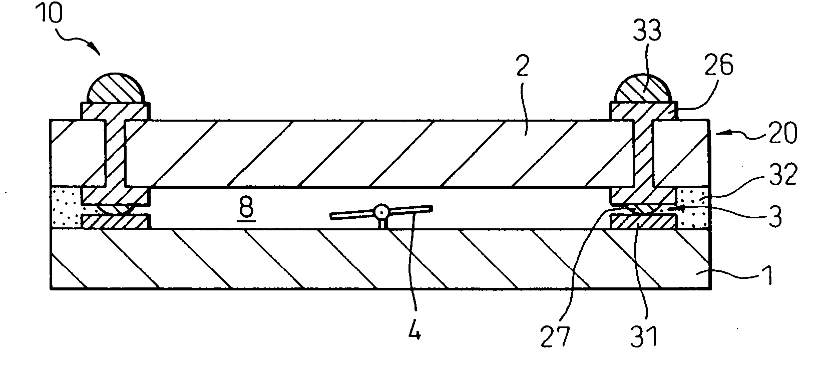
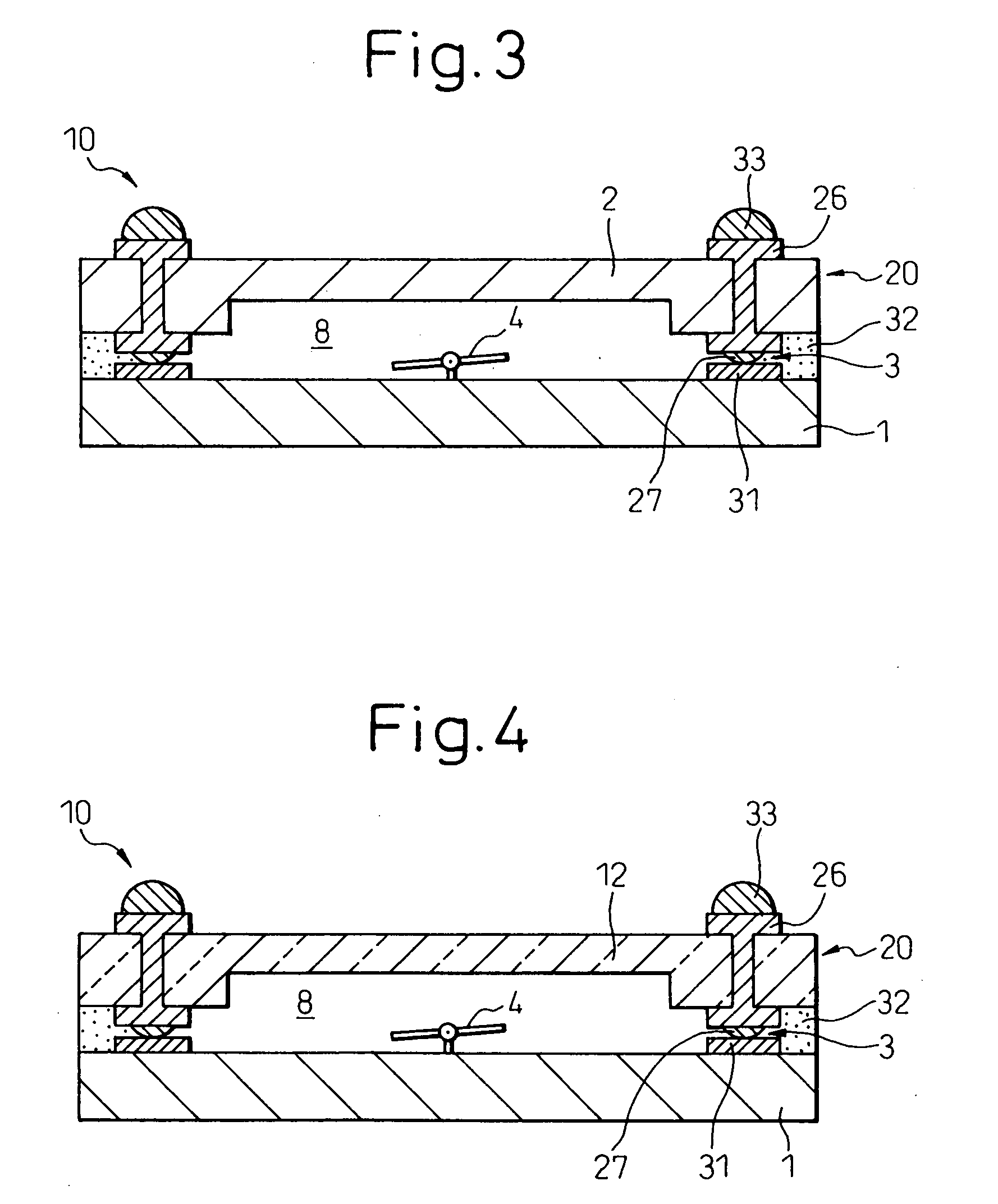
[0138] In this example, a suitable method of production of the MEMS element mounting electronic device shown in FIG. 3 will be explained with reference to FIGS. 11A to 11M.

[0139] First, as shown in FIG. 11A, a silicon wafer 2 is prepared and is washed and dried to remove dirt and the like from the wafer surface.

[0140] Next, as shown in FIG. 11B, a photoresist 21 is coated at a predetermined thickness on one surface of the silicon wafer 2 and patterned to match with the cavity and through holes to be formed. The obtained resist pattern 21 is used as a mask to etch the underlying silicon wafer 2, thereby forming the cavity 12 and through holes (not yet completely opened) 24.

[0141] Here, the silicon wafer may be etched using various methods. For example, plasma etching, sputter etching, reactive ion etching, and other dry etching processes or wet etching processes using an etching solution may be used. In the case of plasma etching, for example, CF4, SF6 and the like may be used as ...

example 2

[0154] In this example, a suitable method for producing an MEMS element mounting electronic device explained in FIG. 5 in accordance with the technique described in Example 1 will be explained with reference to FIGS. 13A to 13D.

[0155] In this example, in addition to forming the copper wiring patterns 26 and the gold stud bumps 27 in accordance with the manner described in Example 1, as shown in FIG. 13A, a frame-like sealing pattern (seal ring) 46 is formed by copper electroplating on one surface (side to be bonded with MEMS substrate) of the circuit substrate 20, then a plating layer (for example, tin plating, gold plating and the like) 47 is formed over that. Note that in place of gold stud bumps 27, it is also possible to form bumps by gold plating at the same time as forming the plating layer 47.

[0156] In addition to the circuit substrate 20, the MEMS substrate 1 is also subjected to similar treatment. That is, as shown in FIG. 13B, in addition to forming the Al electrodes 31 ...

example 3

[0160] In this example, a modification of an MEMS element mounting electronic device shown in FIG. 3 and a preferred production method of the same will be explained with reference to FIGS. 14A to 14C. Using the production method described in this example, it is possible to provide an electronic device with a greater number of functions by building a semiconductor circuit into a silicon wafer or forming a capacitor, resistor, or other passive elements by a thin-film formation process and the like. Further, in this example, a silicon wafer is used, but, needless to say, it is possible to use a glass substrate or other substrate instead of the silicon wafer.

[0161] As shown in FIG. 14A, a silicon wafer 2 is prepared and a semiconductor circuits 28 are fabricated into its back surface (back surface of cavity-forming side). Next, as shown in FIG. 14B, a photoresist 21 is coated at a predetermined thickness on one surface of the silicon wafer 2 and is patterned in accordance with the cavi...


PUM

PropertyMeasurementUnit
Thicknessaaaaaaaaaa

Abstract

An electronic device having mounted thereon an MEMS element or other functional elements, in which a device body and lid define an element-carrying space, the element-carrying space is sealed air-tight by an ultrasonic bonded part bonding the device body and the lid, and the element-carrying space having arranged inside it a system element secured to the device body and/or the lid by flip-chip connection.

Description

BACKGROUND OF THE INVENTION [0001] 1. Field of the Invention [0002] The present invention relates to an electronic device, more particularly to an air-tightly sealed electronic device having mounted thereon a microelectromechanical system element or other functional elements, and a method of production of the same. The present invention also relates to an improved method of securing a lid useful for production of such an electronic device. [0003] 2. Description of Related Art [0004] In recent years, functional components, functional elements, functional devices and the like based on microelectromechanical systems (MEMS) (hereinafter referred to overall as “MEMS elements”) have come into attention. MEMS elements are extremely small in size, yet exhibit complicated and sophisticated functions. An MEMS element usually comprises a substrate having formed integrally with its active surface a mechanically operating micromachine structure (hereinafter referred to as a “micromachine compone...

Claims


Application Information

Patent Timeline
IPC IPC(8): B81B7/00B81C3/00H01L23/02B81B1/00H01L23/04H01L23/053H01L23/10
CPCB81B7/007H01L23/053H01L2924/1461H01L2924/3025H01L2224/45144H01L2224/73265H01L2224/48091H01L2224/16H01L23/10H01L2924/00014H01L2924/00H01L2224/0401H01L23/04
Inventor HIGASHI, MITSUTOSHI
Owner SHINKO ELECTRIC IND CO LTD
Why Eureka
Try Eureka