Method of collecting carbon dioxide contained in fumes

a carbon dioxide and fume technology, applied in the direction of hydrogen sulfide, separation process, sulfur compound, etc., can solve the problems of limited capacity, special attention, and the chemical instability of alkanolamine-based solvents, and the tendency of cosub>2/sub

Inactive Publication Date: 2005-08-04
INST FR DU PETROLE
View PDF11 Cites 92 Cited by
  • Summary
  • Abstract
  • Description
  • Claims
  • Application Information

AI Technical Summary

Benefits of technology

[0015] b) regenerating the carbon dioxide-laden solvent by distillation in a column, a gas being injected into the column, so as to obtain a regenerated solvent and a gaseous effluent comprising carbon dioxide, the volume flow rate of said gas being less than 10% of the volume flow rate of the fumes to be treated in stage a).

Problems solved by technology

On the other hand, their drawback lies in their limited capacity and in a slow chemical association with CO2 as regards material transfer phenomena, which implies that particular attention has to be paid to the dimensioning of the absorbers.
The main drawback of these alkanolamine-based solvents lies in their chemical instability, partly towards CO2, but also towards SOx and oxygen.
The products of these reactions are carboxylic acids that may initiate corrosion problems.
The use of such additives in the case of fumes treatment has to be questioned because of their instability, notably towards oxygen.
This nitrogen co-absorption is in most cases disadvantageous.
However, with low-pressure fumes, this regeneration mode does not allow to obtain a sufficient solvent purity to reach the desired efficiency in the decarbonation stage.
The drawback however is the energy required for this vaporization, which can reach 70% of the energy consumption of the regeneration stage.
Within the context of aqueous alkanolamine or carbonate solutions, or in the case of physical solvents such as methanol or mixtures of polyethylene glycol and water, the vapour stripping effect is readily obtained by evaporation of an amount of solvent, however at the cost of a high energy consumption.
In the case of a solvent of very low vapour pressure, such as an ionic liquid, this stripping effect is generally difficult to obtain.
During the regeneration by distillation stage, the amounts of water released by the ionic solvent are not sufficient to provide this stripping effect.
The result is only partial regeneration of the solvent as regards CO2 and the decarbonation efficiency cannot be obtained.

Method used


Image

  • Method of collecting carbon dioxide contained in fumes

Examples


case 1

[0052] Case 1

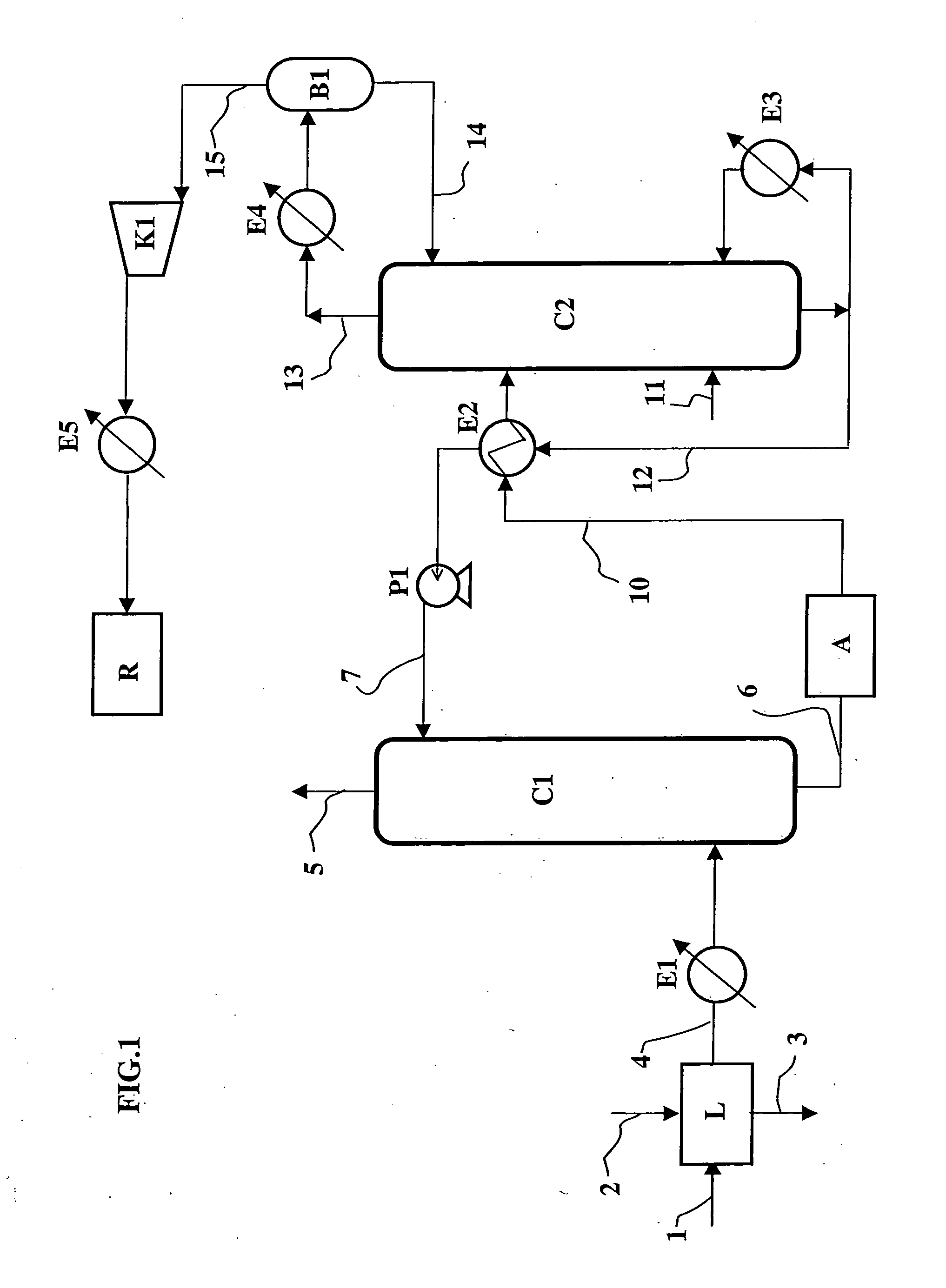
[0053] The solvent used is an aqueous solution containing 30% by weight of MEA (monoethanolamine). In order to collect 90% of the CO2, a flow rate of 2400 m3 / h of an aqueous solution is injected at the inlet of C1. Regeneration of this solution obtained at the bottom of C1 is carried out by distillation, at a pressure of 0.17 MPa abs. at the top of column C2. The temperatures at the bottom and at the top of column C2 are respectively 122° C. and 40° C. to allow regeneration of the solvent.

[0054] Considering the thermal exchange in exchanger E2 between the carbon dioxide rich and poor solutions, an amount of heat equal to 120 Gcal / h is supplied through reboiler E3 of column C2.

case 2

[0055] Case 2

[0056] The solvent used is a tetraethylene glycol dimethyl ether solution containing 30% by weight of MEA (monoethanolamine). To collect 90% of the CO2, a 2600 m3 / h flow rate of solvent is injected at the inlet of C1. Regeneration of this solution obtained at the bottom of C1 is carried out by distillation, at a pressure of 0.17 MPa abs. at the top of column C2. To favour regeneration of the solvent, 1% of the flow of decarbonated fumes obtained at the top of column C1 is fed into the bottom of regeneration column C2, this stream of fumes allowing to strip the carbon dioxide contained in the solvent. The temperatures at the bottom and at the top of column C2 are then respectively 125° C. and 40° C. to allow regeneration of the solvent. Considering the thermal exchanges, on the one hand, between the carbon dioxide-rich solution and the stripping fumes in C2 and, on the other hand, between the carbon dioxide rich and poor solutions in heat exchanger E2, it is necessary to...


PUM

PropertyMeasurementUnit
vapour pressureaaaaaaaaaa
temperatureaaaaaaaaaa

Abstract

The fumes flowing in through line 1 are contacted in column C1 with a solvent, at low vapour pressure, absorbing the carbon dioxide. The solvent laden with carbon dioxide is regenerated by distillation in column C2. In order to improve the regeneration operation, a gas is injected through line 11 into column C2 so that this gas carries along the carbon dioxide contained in the solvent. The carbon dioxide-rich gaseous effluent obtained at the top of column C2 can be liquefied by compression and cooling, then stored in surge tank R, which allows its transportation and possibly underground sequestration.

Description

FIELD OF THE INVENTION [0001] The present invention relates to a method of collecting carbon dioxide contained in combustion fumes. BACKGROUND OF THE INVENTION [0002] Atmospheric pollution is a phenomenon which gains in importance, as regards the emission sources as well as the amounts of compounds emitted and the impact of the pollution on man and on the environment. Carbon dioxide (CO2) is one of the greenhouse effect gases widely produced by man's various activities, notably by the combustion of hydrocarbons. [0003] In order to reduce the amounts of carbon dioxide discharged to the atmosphere, it is possible to collect the carbon dioxide contained in industrial fumes, which are fixed and important sources. [0004] There are methods of collecting carbon dioxide by fumes washing using a solvent. The physico-chemical characteristics of the solvents used are closely linked with the nature of the fumes: selective elimination of an impurity, thermal and chemical stability of the solvent...

Claims


Application Information

Patent Timeline
Patent Type & Authority Applications(United States)
IPC IPC(8): B01D53/62B01D53/14C01B32/50
CPCB01D53/1425Y02C10/06Y02C10/04B01D53/1475Y02C20/40
Inventor CADOURS, RENAUDCARRETTE, PIERRE-LOUISMOUGIN, PASCALBROUTIN, PAULBOUCOT, PIERRE
Owner INST FR DU PETROLE
Why Eureka
Try Eureka