Organic electroluminescent device and method for manufacturing the same

a technology of electroluminescent devices and electroluminescent devices, which is applied in the direction of discharge tube luminescence screens, natural mineral layered products, transportation and packaging, etc., can solve the problems of insufficient life properties of devices, inability to obtain great luminescence intensity, and inability to know the details of the process, etc., to achieve stable operation, excellent life properties, and stable electron injection

Inactive Publication Date: 2005-08-04
JOLED INC
View PDF17 Cites 238 Cited by
  • Summary
  • Abstract
  • Description
  • Claims
  • Application Information

AI Technical Summary

Benefits of technology

[0019] In view of such practical circumstances, an object of the present invention is to provide an organic EL device which can be driven over a wide range of from low brightness used in display applications to high brightness used in light source applications, which works stably over a wide range of brightness, and which has excellent life property.
[0020] Further, another object of the present invention is to provide a method for easily manufacturing an organic EL device which works stably and has excellent life property.

Problems solved by technology

However, there are still two problems to be solved, such as that sufficiently great luminescence intensity cannot be obtained, and that the device does not have a sufficient life property when driving for a long period of time.
However, details of the process are not yet known, and an extensive study thereon is still being carried out.
However, a mixture of polymeric materials in general is likely to undergo phase separation owing to the delicate difference in the solubility to a solvent, and this is not an exception to PEDOT (Applied Physics Letters, Vol. 79, pp.
To undergo phase separation means that the moderate bonding of the two polymers is relatively easily breakable, and it implies that when PEDOT is driven in an organic EL device, it may be possibly unstable, or as a result of phase separation, may have adverse effects on other functional layers upon diffusion of a component not involved in the bonding, in particular an ionic component, caused by the electric field resulting from electric current flow.
Thus, despite its excellent charge injection property, PEDOT is not considered as a stable substance.
Even though this certainly improves the efficiency of the device as compared with the case where nothing is disposed between the ITO electrode and the light emitting layer, the properties of the device are rather poorer when compared with a device having a PEDOT layer.
Therefore, there is a limit in the brightness obtained, and it is not possible to obtain higher brightness.
Thus, it cannot be said to have the brightness obtainable at a sufficiently satisfactory level, and the durability is not sufficient, either.
In these examples, the reason for insufficient durability of the device is considered to be attributable to the high barrier between the electrode and the hole transport layer or the light emitting layer and too much voltage applied on this barrier.

Method used


Image

  • Organic electroluminescent device and method for manufacturing the same
  • Organic electroluminescent device and method for manufacturing the same
  • Organic electroluminescent device and method for manufacturing the same

Examples


embodiment 1

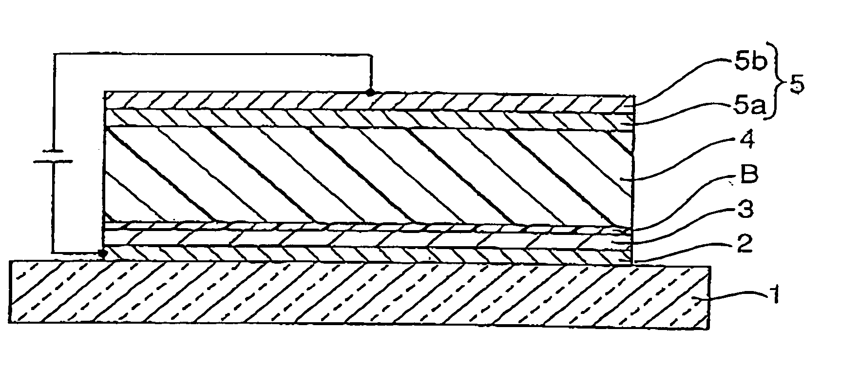
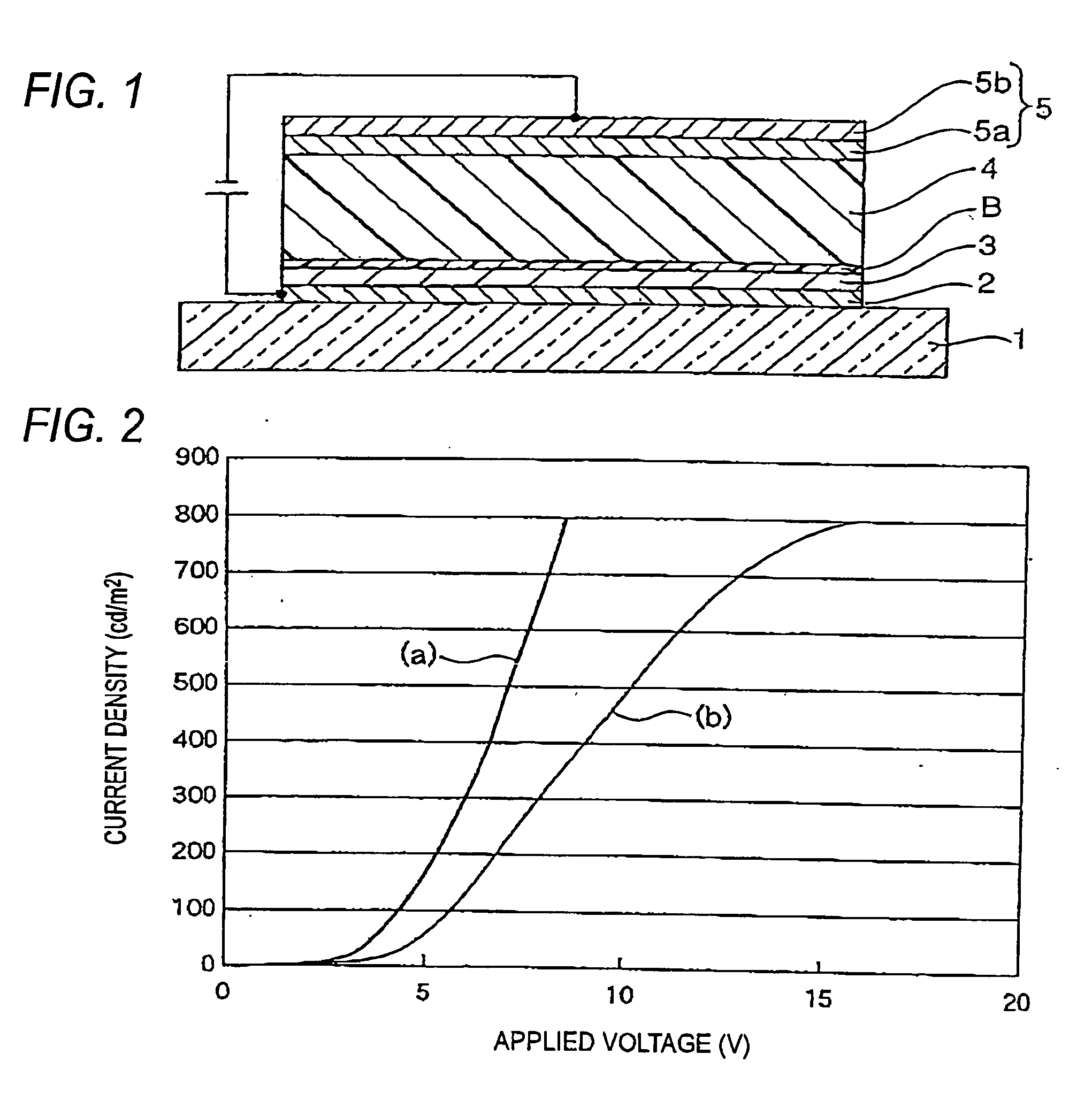
[0073]FIG. 1 is a schematic diagram of the polymeric organic EL device according to the embodiment of the invention.

[0074] The present embodiment is characterized in that a thin film of metal oxide is formed as a charge injection layer 3 on a transparent anode 2 formed on a light transmitting substrate 1, and laminated thereon are a layer of polymeric material as a buffer layer B having the electron-blocking function, and another layer of polymeric material as a light emitting layer 4, with a cathode 5 being formed above them all.

[0075] That is to say, the organic electroluminescent device of the embodiment consists of, as shown in FIG. 1, substrate 1 made of a transparent glass material, an ITO layer (indium titanium oxide) as an anode 2 formed on the substrate 1, a thin film of metal oxide as charge injection layer 3 formed thereon, an electron-blocking layer made of a polymeric material as buffer layer B, light emitting layer 4 made of a polymeric material, and a cathode 5 made...

example 1

[0082] Next, Examples of the invention will be presented.

[0083] The structure is identical with the structure given in FIG. 1, and it will be explained with reference to FIG. 1.

[0084] The organic electroluminescent device of Example 1 is composed of a substrate 1 made of a 1 mm-thick glass sheet referred to as Corning 7029#, an anode 2 composed of a 20 nm-thick ITO thin film formed thereon, a charge injection layer 3 composed of a 20 nm-thick thin film of molybdenum oxide formed on the anode 2, a 20 nm-thick buffer layer B of a polyfluorene-based compound, in particular poly[9,9-dioctylfluorenyl-2,7-diyl]-alt-co-(N,N′-diphenyl)-N,N′-di(p-butyl-oxyphenyl)-1,4-diaminobenzene, formed on the charge injection layer 3, a 80 nm-thick light emitting layer 4 composed of a polyfluorene-based compound, in particular poly[(9, 9-dioctylfluorenyl-2,7-diyl)-o-1,4-benzo-{2, 1′-3}-thiadiazole, and a cathode 5 which is formed on the light emitting layer 4 and is composed of a 20 nm-thick calcium (C...

example 2

[0124] Next, Example 2 of the invention will be discussed.

[0125] In Example 1 above, a polyfluorene-based compound was used in the light emitting layer, but this Example uses a PPV-based material, poly[2-methoxy-5-(2-ethylhexyloxy)-1,4-phenylenevinylene], in the light emitting layer 4. This material is also commercially available from Nihon SiberHegner KK., like Example 1.

[0126] The other structures are constituted identically with Example 1.

[0127] In this case, the luminescence intensity can be increased further in the universal.

[0128] Furthermore, in Example 1 and Example 2 a glass substrate was used as the substrate 1, but it is not limited to glass. Generally glass is used. Also in the present Example, a glass substrate is employed. There have been proposed as the substrate material, a number of materials including glass, plastic film and the like, and these all can be employed as the substrate 1 in the present invention. In addition, if the direction of light extraction is ...


PUM

PropertyMeasurementUnit
thicknessaaaaaaaaaa
thicknessaaaaaaaaaa
current densityaaaaaaaaaa

Abstract

An organic EL device which drives over a wide range from low brightness to high brightness for light source applications, operates stably over a wide range of brightness and has excellent life property is provided. The device comprises at least one pair of electrodes 2 and 5, and a plurality of functional layers disposed between the electrodes 2 and 5, the functional layers comprising a layer 4 having the light emitting function, which is composed of at least one polymeric material and contains an organic solvent and a charge injection layer 3 composed of at least one inorganic material.

Description

BACKGROUND OF THE INVENTION [0001] 1. Field of the Invention [0002] The present invention relates to an organic electroluminescent device (hereinafter, abbreviated to an “organic EL device”) which is an electroluminescent device used in various displays such as the display for cellular phones and various light sources, and to a method for manufacturing the same, and more particularly to an organic EL device comprising a polymeric luminescent material in an organic thin film, which can be driven in a wide range of brightness, from that of low brightness used in various display applications to high brightness used in light sources. [0003] 2. Description of the Related Art [0004] Generally, organic EL devices are light emitting devices which utilizes the phenomenon of electroluminescence exhibited by solid fluorescent substances, and such organic EL devices have been widely put to practical use as miniature displays. [0005] Organic EL devices can be classified to two types by the diffe...

Claims


Application Information

Patent Timeline
Patent Type & Authority Applications(United States)
IPC IPC(8): H01L51/00H01L51/30H01L51/50
CPCC09K11/06C09K2211/1425H01L51/0038H01L51/0039Y10T428/24942H01L51/5088H01L51/5096H05B33/14Y10S428/917H01L51/5012H10K85/114H10K85/115H10K50/17H10K50/18H10K50/11H10K50/171
Inventor YATSUNAMI, RYUICHISAKANOUE, KEI
Owner JOLED INC
Why Eureka
Try Eureka