Configurations and methods of acid gas removal

a technology of acid gas removal and feed gas, which is applied in the direction of liquid degasification, separation process, dispersed particle separation, etc., can solve the problems of uneconomical use, unsatisfactory use effect, and increase the cost of such operations

Active Publication Date: 2005-08-11
FLUOR TECH CORP
View PDF9 Cites 85 Cited by
  • Summary
  • Abstract
  • Description
  • Claims
  • Application Information

AI Technical Summary

Benefits of technology

[0011] Therefore, in one particularly preferred aspect of the inventive subject matter, a plant will include a vacuum stripper that is configured to produce an ultra-lean physical solvent from a lean hydrogen sulfide-containing physical solvent. Contemplated plants will further include a high-pressure flash vessel and/or a medium pressure flash vessel that provide a substantially hydrogen sulfide-free stripping gas to the vacuum stripper.
[0012] Further contemplated plants include an absorber that operates with an isothermal gradient or with a decreasing top-to-bottom thermal gradient, and that receives

Problems solved by technology

Such acid gas removal and sulfur plant combinations are generally energy intensive and costly.
Moreover, in today's diminishing sulfur market the so produced sulfur is only of little commercial value and is consequently disposed of, which still further increases cost for such operations.
However, all or almost all single stage membrane separators are relatively non-selective and therefore produce a carbon dioxide permeate stream with a relatively high methane and hydrocarbon content (which is either vented, incinerated, or used as a low BTU fuel gas).
Consequently, the relatively high methane and hydrocarbon losses often render the use of this process undesirable and uneconomical.
However, such systems are often energy intensive and costly.
However, the refrigerant cooling requirement to maintain the solvent at cryogenic temperatures is relatively high, and the process often exhibits greater than desired methane and ethane absorption, thereby necessitating large energy input for recompression and recovery.
However, i

Method used


Image

  • Configurations and methods of acid gas removal
  • Configurations and methods of acid gas removal
  • Configurations and methods of acid gas removal

Examples


Embodiment Construction

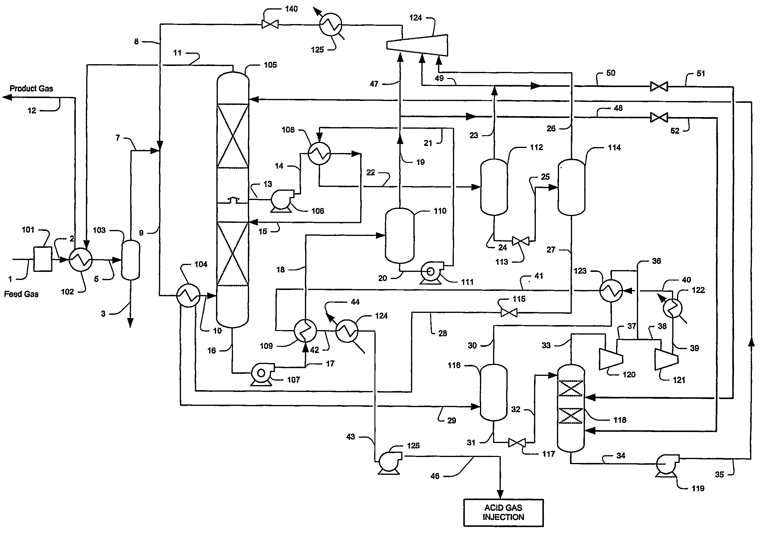
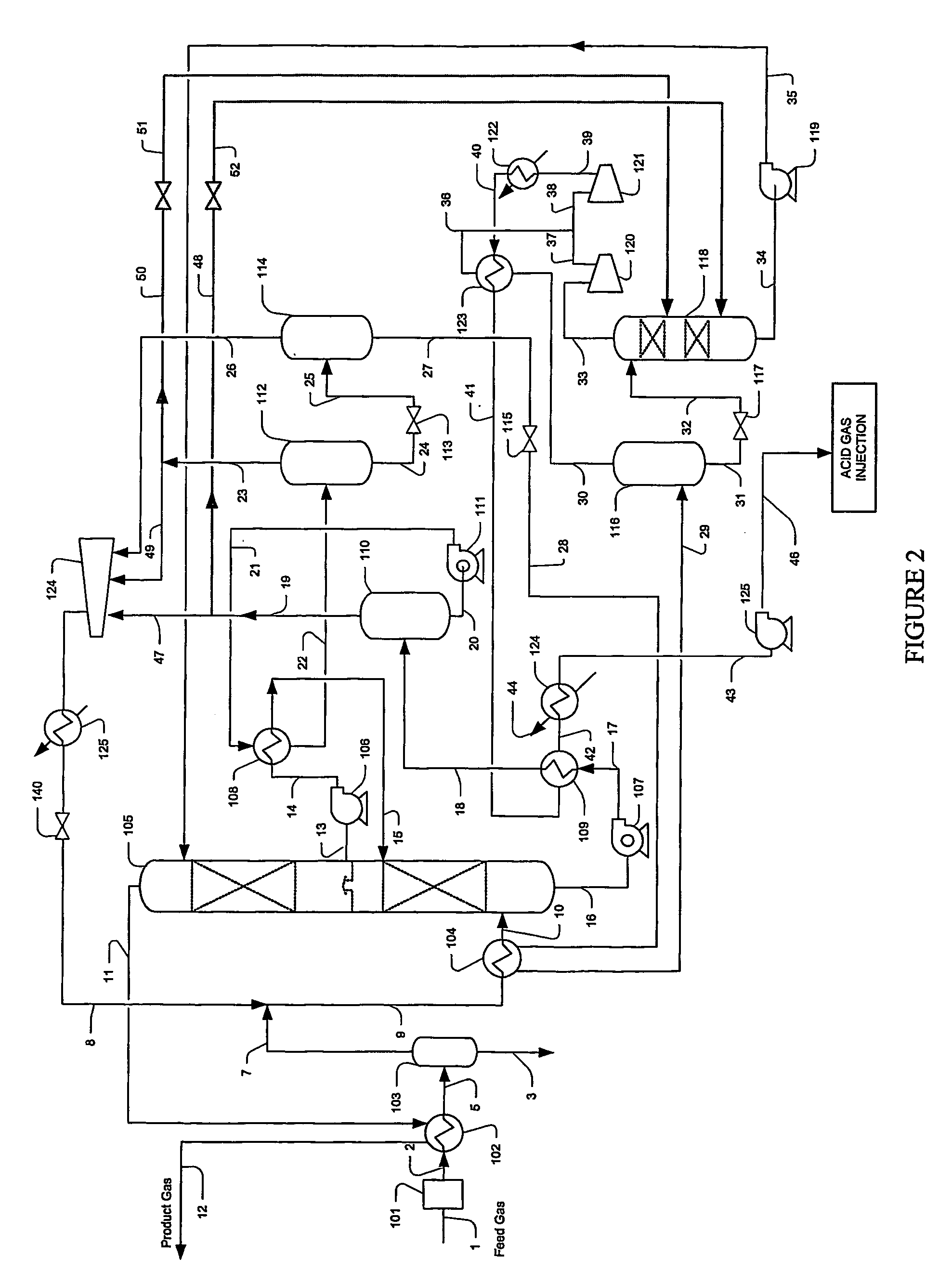
[0018] The inventors have discovered that acid gases, and particularly carbon dioxide, is removed from a feed gas comprising carbon dioxide and hydrogen sulfide in configurations and methods in which flashed gases from the feed gas are employed to strip hydrogen sulfide from a lean physical solvent that is employed to also remove carbon dioxide.

[0019] In particularly preferred configurations, it is contemplated that a stripper operates under vacuum pressure (typically between about 1 to 10 psia), wherein the stripping gas is supplied from the high pressure and medium pressure flash in the solvent regeneration process. It is further preferred that the conditions in the high pressure and medium pressure flash and the quantities of the flashed gases are preferably selected such that the flash gases contain mostly light hydrocarbons and some carbon dioxide, but are substantially free (i.e., less than 1000 ppm, typically less than 100 ppm, and more typically less than 10 ppmv of hydroge...


PUM

PropertyMeasurementUnit
Fractionaaaaaaaaaa
Fractionaaaaaaaaaa
Fractionaaaaaaaaaa

Abstract

A plant includes a vacuum stripper (118) that receives a lean hydrogen sulfide-containing physical solvent (32) and in which substantially hydrogen sulfide-free stripping gas (51,52) is provided by at least one of a high-pressure flash vessel (110) and a medium pressure flash vessel (112). Contemplated configurations advantageously extend the range of use for physical solvents to treat sour gas comprising carbon dioxide and hydrogen sulfide, and can be used to meet most pipeline specification of 4 ppm hydrogen sulfide.

Description

[0001] This application claims the benefit of U.S. provisional patent application with the Ser. No. 60 / 433,257, which was filed Dec. 12, 2002, and which is incorporated by reference herein.FIELD OF THE INVENTION [0002] The field of the invention is removal of acid gases from a feed gas, and particularly relates to acid gas removal from high carbon dioxide and hydrogen sulfide content feed gas. BACKGROUND OF THE INVENTION [0003] Acid gas removal from various gas streams, and especially removal of carbon dioxide from natural gas streams has become an increasingly important process as the acid gas content of various gas sources is relatively high, or increases over time. For example, various natural gas sources in Alaska, continental North America, Norway, Southeast Asia, or in the gulf of Mexico contain carbon dioxide ranging from about 20% to about 75%. Furthermore, acid gas from various gas fields also contains hydrogen sulfide at significant concentrations that typically needs to b...

Claims


Application Information

Patent Timeline
IPC IPC(8): B01D53/14
CPCB01D53/1425B01D53/1456Y02C10/06B01D53/1493B01D53/1462Y02C20/40
Inventor MAK, JOHN
Owner FLUOR TECH CORP
Why Eureka
Try Eureka