Battery

a battery and three-dimensional technology, applied in the field of batteries, can solve the problems of high power, complex equipment, high power, etc., and achieve the effects of reducing production costs, reducing production costs, and increasing capacity (electric power amount) of batteries

Inactive Publication Date: 2005-08-11
KAWASAKI HEAVY IND LTD
View PDF7 Cites 45 Cited by
  • Summary
  • Abstract
  • Description
  • Claims
  • Application Information

AI Technical Summary

Benefits of technology

[0064] (1) In the three-dimensional battery of the present invention, since the capacity (electric power amount) of the battery can be increased by increasing a volume of each cell, the enlargement of scale results in advantages in production cost. In addition, since the battery is the fixed layers, its structure can be simplified.
[0065] (2) Since the voltage is determined by the type (material) of the active material filled in the shape of particles within the cells, it is necessary to connect a plurality of unit batteries in series to gain a large voltage. Since the current collecting members of both electrodes of the unit batteries are made of a common material, and a cathode electrode and an anode electrode are not formed unlike in the conventional battery, the electrically conductive current collecting members define the spacing between the cells (unit batteries) to enable electrical and structural series connection, and the thickness of the batteries can be reduced. So, the whole battery can be made compact and small-sized. In addition, since the current flows in the thickness direction, a large current flows without substantial resistance.
[0066] (3) Further, the active material particles function as a membrane (battery body) of the conventional battery of a membrane structure, and the current flowing through the battery is directly proportional to the surface area of the active materials. The active material particles form fixed layers in the electrolytic solutions. And, a total surface area of the whole active material particles becomes several tens hundred to several hundreds hundred times as large as that of the conventional battery of the membrane structure. So, the power density becomes several tens hundred to several hundreds hundred times higher. Also, since the active material particles are put into the electrolytic solution (dilute sulfuric acid in lead battery) to be mixed and used, the degraded active material particles and the electrolytic solution are replaced, thus recovering the active material particles. As a result, the life of the battery can be significantly extended.
[0067] (4) When electrically conductive studs are provided to extend from the current collecting members or the current collectors toward inside of the cells, a contact area between the current collecting members or the current collectors and the active material particles significantly increases, and contact resistance decreases. Thereby, the width of the cells (spacing between cells in the series direction) can be increased, and the capacity of the battery can be significantly increased.

Problems solved by technology

In the battery disclosed in this publication, a high power can be gained but equipment becomes intricate.
In a three-dimensional battery of a fluidized layer type disclosed in Japanese Patent Publication No. 3051401, high power can be gained but equipment thereof becomes intricate.
However, the above conventional batteries have drawbacks as described below.
(1) Enlargement of scale is limited or impossible.
In either case, the battery becomes huge and is difficult for practical use.
Consequently, the batteries must be connected in parallel, and thereby, the whole structure becomes intricate.
Even if the number of membranes is increased as a solution to this, the enlargement of scale is impossible.
(2) Degradation of active materials or catalysts cannot be dealt with.
In actuality, such replacement is impossible and the degraded battery is discarded.
(3) A heat transfer surface for exothermic reaction and endothermic reaction in association with charge and discharge cannot be installed.
But, since the conventional battery has an intricate structure, the heat transfer surface can not installed.
And, the upper limit temperature is set by using a temperature fuse but any temperature control device is not installed within the battery.
Consequently, the energy density cannot be increased.
(5) A production cost of a battery having a large capacity is extremely high.
In case of the battery of the membrane structure, if it is made to obtain the large capacity, the area of the membrane must be correspondingly increased, and the production cost becomes higher with an increase in the battery capacity.
For this reason, enlargement of the scale results in no advantage in production cost.
(6) When the batteries are connected in series, a device cost is high and a resistance energy loss in a connected portion is large.
The manufacturing cost therefore becomes high and heat loss generated due to the current passing through the connected portion causes an energy loss.

Method used


Image

  • Battery
  • Battery
  • Battery

Examples


first embodiment

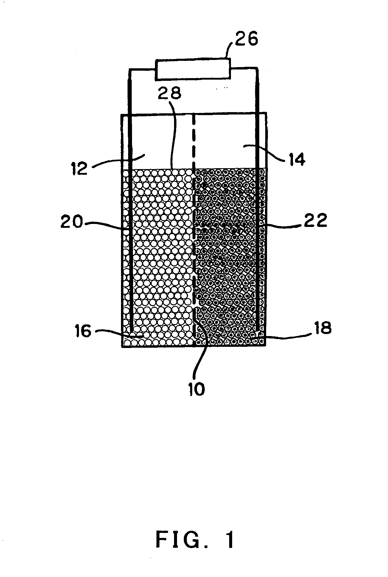
[0095]FIG. 1 shows a battery according to the present invention. As shown in FIG. 1, an anode cell 12 and a cathode cell 14 are provided with an ion permeable filter (separator) 10 interposed therebetween. The anode cell 12 is filled with anode active material particles and an electrolytic solution 16, and the cathode cell 14 is filled with a cathode active material particles and an electrolytic solution 18. The active material particles exist in the electrolytic solutions as fixed layers. In FIG. 1, and FIGS. 2 through 20, the size of the active material particles is the same for the sake of convenience, but actually, the size may vary as a matter of course.

[0096] Examples of a combination of the active material particles for the anode and the cathode are hydrogen-occluding alloy and nickel hydroxide, cadmium and nickel hydroxide, etc. An example of the hydrogen-occluding alloy is La0.3 (Ce, Nd)0.15 Zr0.05 Ni3.8 Co0.8 Al0.5. As the electrolytic solution, for example, a KOH aqueous ...

second embodiment

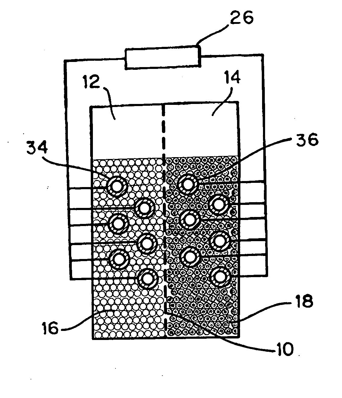
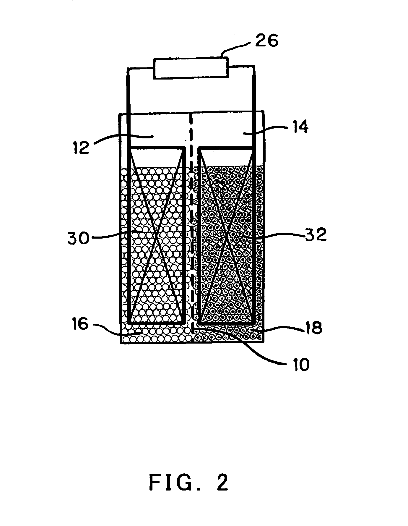
[0101]FIGS. 2 and 3 show a battery according to the present invention. FIG. 2 shows the battery structured such that an anode current collector and a cathode current collector are plate-shaped anode current collectors 30 and plate-shaped cathode current collectors 32 for increasing contact area for the purpose of improving the contact efficiency between the current collectors and the active material particles. FIG. 3 shows the battery structured such that an anode current collector and a cathode current collector are pipe-shaped anode current collectors 34 and pipe-shaped cathode current collectors 36 for increasing contact area for the purpose of improving the contact efficiency between the current collectors and the active material particles. Other than the plate and the pipe, shapes that allow the surfaces areas of the current collectors to increase may be employed.

[0102] The other constitution and function are similar to those of the first embodiment.

third embodiment

[0103]FIGS. 4 and 5 show a battery according to the present invention. As shown in FIG. 4, an anode current collector 38 and a cathode current collector 40 are provided within the fixed layers. And, as shown in FIG. 5, an anode current collector 42 and a cathode current collector 44 are agitators driven to rotate by a motor or the like (not shown), respectively.

[0104] In the battery in FIG. 4, agitation means such as vane-shaped agitators may be provided within the cells 12 and 14.

[0105] As shown in FIG. 5, the anode current collector and agitator 42 and the cathode current collector and agitator 44 serve to agitate the active material particles and directly contact the active material particles. The vane-like agitators or the like which are driven to rotate by motors or the like (not shown) may be used as the anode current collector and agitator 42 and the cathode current collector and agitator 44, but the constitution of the agitating means is not limited.

[0106] The other consti...


PUM

PropertyMeasurementUnit
areaaaaaaaaaaa
areaaaaaaaaaaa
areaaaaaaaaaaa

Abstract

Anode active material particles and an electrolytic solution 16 are filled in an anode cell 12 as one of two vessels connected to each other with an ion-permeable separator 10 interposed therebetween, and cathode active material particles and an electrolytic solution 18 are filled in a cathode cell 14 as the other vessel. Electrically conductive current collectors 20 and 22 are provided in contact with the active material particles within the two vessels. The active material particles form fixed layers.

Description

TECHNICAL FIELD [0001] The present invention relates to a battery of a fixed-layer type, which is formed by active material particles with a simple structure and is capable of storing a huge electric power. The present invention relates to a three-dimensional battery with a simple structure which is formed by a fixed layer by putting active material particles adapted to discharge and adsorb electrons in an electrolytic solution filled in a cell (vessel) as minimum electrodes, and is capable of storing an electric power of a large capacity. BACKGROUND ART [0002] Conventionally, a battery is structured in a way that an active material having the shape of plate or sheet is immersed in an electrolytic solution. And, a plate-shaped separator is disposed between a cathode and an anode, thereby forming an electrode structure. [0003] For example, Japanese Laid-Open Patent Provisional Publication No. Hei. 7-169513 discloses a method and device that reproduce a battery material after discharg...

Claims


Application Information

Patent Timeline
Patent Type & Authority Applications(United States)
IPC IPC(8): H01M2/38H01M4/02H01M4/38H01M4/52H01M4/58H01M6/42H01M6/50H01M8/18H01M10/06H01M10/34H01M10/36H01M10/42H01M10/50
CPCH01M2/385Y02E60/528H01M4/383H01M6/42H01M6/5022H01M6/5038H01M6/5077H01M8/188H01M10/06H01M10/345H01M10/4214H01M10/4242H01M10/5004H01M10/5006H01M10/5032H01M10/5042H01M10/5053H01M10/5057H01M10/5063H01M10/5075H01M10/5095H01M4/02H01M10/615H01M10/663H01M10/647H01M10/654H01M10/6556H01M10/6567H01M10/6554H01M10/6561H01M10/613Y02E60/50Y02E60/10H01M50/73
Inventor TSUTSUMI, KAZUOKUMAGAI, CHIKANORITSUTSUMI, ATSUSHIKUBO, YUKIO
Owner KAWASAKI HEAVY IND LTD
Why Eureka
Try Eureka