Three-dimensional fiber structure of refractory fibers, a method of making it, and thermostructural composite materials, in particular friction parts, made therefrom

a three-dimensional fiber and refractory fiber technology, applied in the field of porous three-dimensional (3d) fiber structure made of refractory fibers, can solve the problem of not being able to distribute fillers in the desired manner within the fiber structure, i.e. in uniform manner or in a manner, and achieve the effect of improving the method of fabricating parts and improving the properties of composite material parts

Active Publication Date: 2005-08-11
CENT NAT DE LA RECHERCHE SCI
View PDF4 Cites 108 Cited by
  • Summary
  • Abstract
  • Description
  • Claims
  • Application Information

AI Technical Summary

Benefits of technology

[0016] An object of the invention is to overcome this difficulty so as to provide 3D fiber structures in satisfactory manner both for improving the ...

Problems solved by technology

Nevertheless, it is found in practice to be impossible to distribute the fillers in desired manner ...

Method used


Image

  • Three-dimensional fiber structure of refractory fibers, a method of making it, and thermostructural composite materials, in particular friction parts, made therefrom
  • Three-dimensional fiber structure of refractory fibers, a method of making it, and thermostructural composite materials, in particular friction parts, made therefrom
  • Three-dimensional fiber structure of refractory fibers, a method of making it, and thermostructural composite materials, in particular friction parts, made therefrom

Examples


example 1

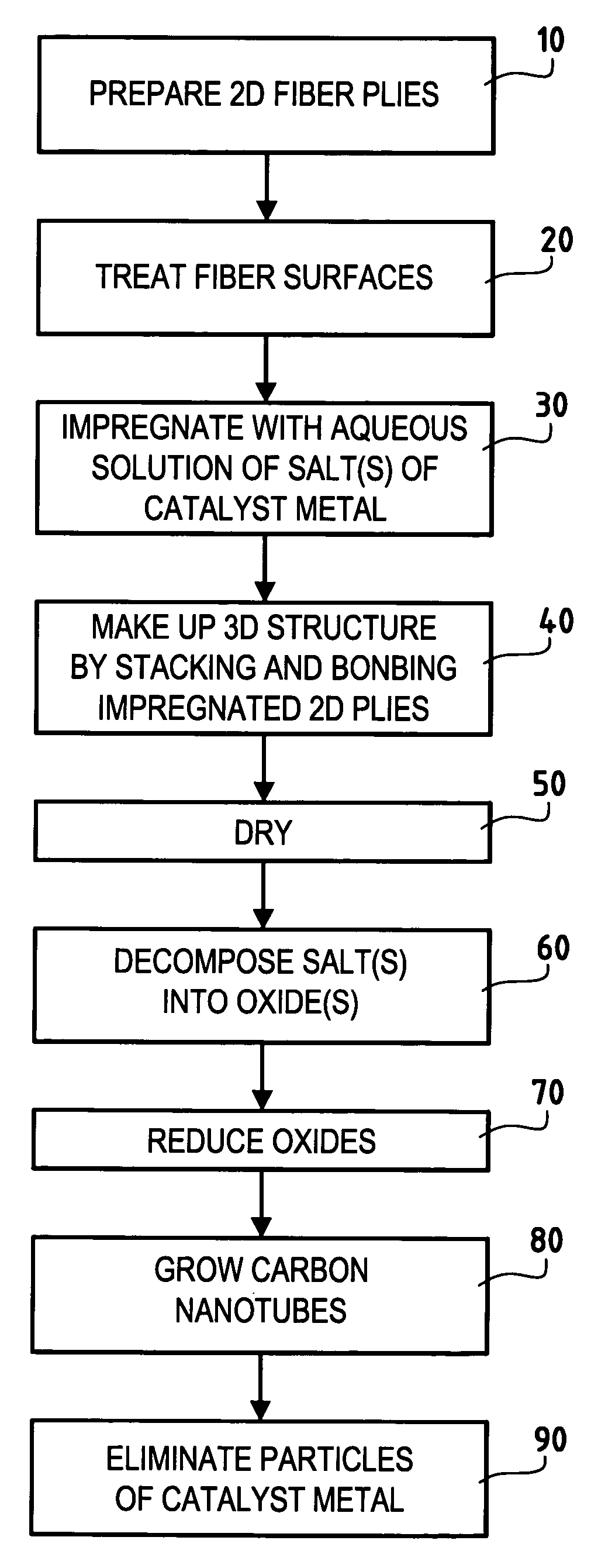
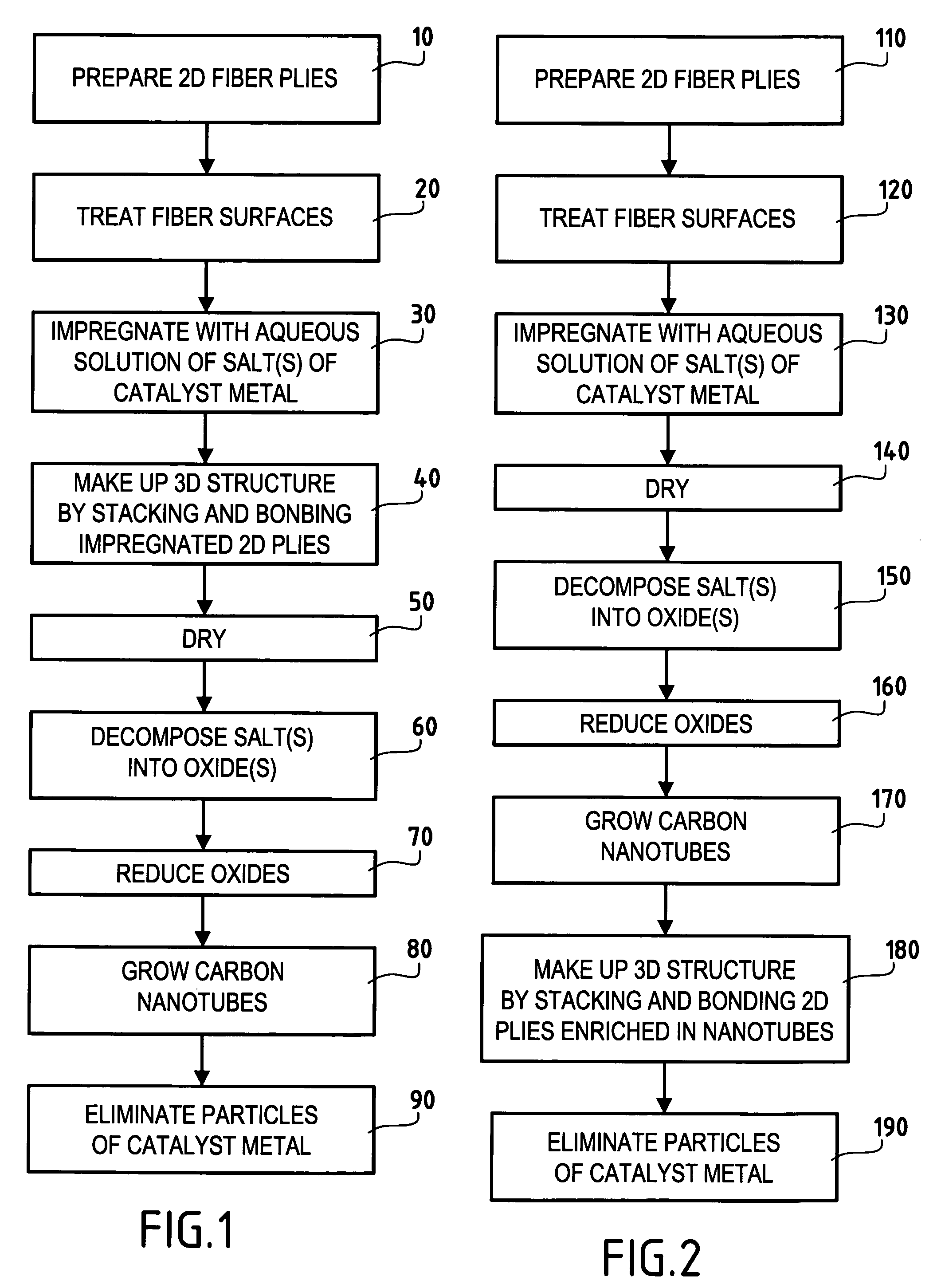
[0115] Carbon cloth plies made of cellulose precursor that had been subjected to carbonization treatment at a temperature of up to 1200° C. were impregnated in a 0.2 molar aqueous solution of iron nitrate. Twenty plies impregnated in this way were stacked and needled to one another. The needling was performed progressively as increasing number of plies were stacked, so as to ensure that the needles penetrated to a substantially constant depth, as described in document U.S. Pat. No. 4,790,052.

[0116] The resulting moist 3D fiber structure was dried in air at 200° C. in a ventilated stove, which also caused the iron nitrate to decompose into oxide. The 3D fiber structure was introduced into an oven where the temperature was raised to 700° C. under an inert atmosphere (nitrogen) to avoid oxidizing the carbon. The oxide was then reduced by introducing a reducing atmosphere into the oven, said atmosphere comprising a mixture of equal volume fractions of ammonia gas and nitrogen for a per...

example 2

[0117] Carbon cloth plies of cellulose precursor of the same kind as in Example 1 were impregnated in a 0.05 molar aqueous solution of iron nitrate.

[0118] The plies were dried under air at 200° C. in a ventilated stove, thereby also causing the iron nitrate to decompose into oxide. The dried plies were introduced into an oven where the temperature was raised to 700° C. under an inert atmosphere (nitrogen). The oxygen was then reduced by introducing a reducing atmosphere into the oven constituted by a mixture of equal volume fractions of ammonia gas and nitrogen for a duration of 30 min. Thereafter, with the temperature being maintained at 700° C., a gas was introduced into the oven comprising acetylene diluted in nitrogen (1 volume of acetylene for 3 volumes of nitrogen) for a duration of 2 h. After cooling to ambient temperature under nitrogen, carbon nanotube growth on the carbon fibers of the plies was observed, and the measured increase in weight relative to the initial cloth p...

example 3

[0121] The same procedure as in Example 2 was performed except that the cloth plies were impregnated with a 0.2 molar aqueous solution of nickel nitrate and the duration of carbon nanotube growth was extended to 10 h instead of 2 h. The measured increase in weight after the cloth plies had been enriched in carbon nanotubes was about 175%.


PUM

PropertyMeasurementUnit
Fractionaaaaaaaaaa
Fractionaaaaaaaaaa
Moment of inertiaaaaaaaaaaa

Abstract

Carbon nanotubes are incorporated in the fiber structure by growing them on the refractory fibers of the substrate so as to obtain a three-dimensional substrate made of refractory fibers and enriched in carbon nanotubes. The substrate is densified with a matrix to form a part of composite material such as a friction part of C/C composite material.

Description

[0001] This is a continuation-in-part of International Application No. PCT / FR2003 / 002692 with an international filing date of Sep. 11, 2003, which claims priority from French patent application No. 02 11302 filed Sep. 12, 2002.BACKGROUND OF THE INVENTION [0002] The invention relates to porous three-dimensional (3D) fiber structures made of refractory fibers. In particular it relates to such structures for constituting fiber preforms for making parts out of thermostructural composite material. [0003] A particular field of application of the invention is the manufacture of friction parts, such as brake disks, having a carbon fiber reinforcement. [0004] Thermostructural composite materials are well known for their good mechanical properties which make them suitable for constituting structural elements, and for their ability to retain these properties at high temperatures. They comprise in particular carbon / carbon (C / C) composite materials having carbon fiber reinforcement densified by ...

Claims


Application Information

Patent Timeline
IPC IPC(8): D04H1/46B29C70/10B29C70/24B32B1/00B32B1/06B32B5/26B82B1/00B82B3/00C01B31/02C04B35/622C04B35/80C04B35/83D01F9/127D01F11/10D01F11/16D04H13/00D06M11/00D06M11/65D06M101/40F16D69/02
CPCB82Y30/00F16D2200/0047C04B35/6268C04B35/63C04B35/80C04B35/83C04B2235/3272C04B2235/3275C04B2235/3279C04B2235/405C04B2235/48C04B2235/5256C04B2235/5288C04B2235/614C04B2235/80C04B2235/96D01F9/1275F16D69/023C04B35/62272Y10T442/667C04B35/515C04B2235/5248C04B2235/5216D01F9/12C04B35/622D01F9/127B82Y40/00
Inventor OLRY, PIERREBRETON, YANNICK CLAUDEBONNAMY, SYLVIENICOLAUS, NATHALIEROBIN-BROSSE, CHRISTIANSION, ERIC
Owner CENT NAT DE LA RECHERCHE SCI
Why Eureka
Try Eureka