
Membrane-electrode structure and method for producing the same

a technology of membrane electrolectrodes and electrodes, which is applied in the direction of cell components, cell component details, electrochemical generators, etc., can solve the problems of electrical short circuit between the catalyst layers b>3/b> and b>4/b>, and the exhaustion of the petroleum source, so as to reduce the adhesive force, prevent the damage of the catalyst, and ensure the effect of a sufficient adhesiveness

Inactive Publication Date: 2005-08-18
HONDA MOTOR CO LTD
View PDF7 Cites 36 Cited by
  • Summary
  • Abstract
  • Description
  • Claims
  • Application Information

AI Technical Summary

Benefits of technology

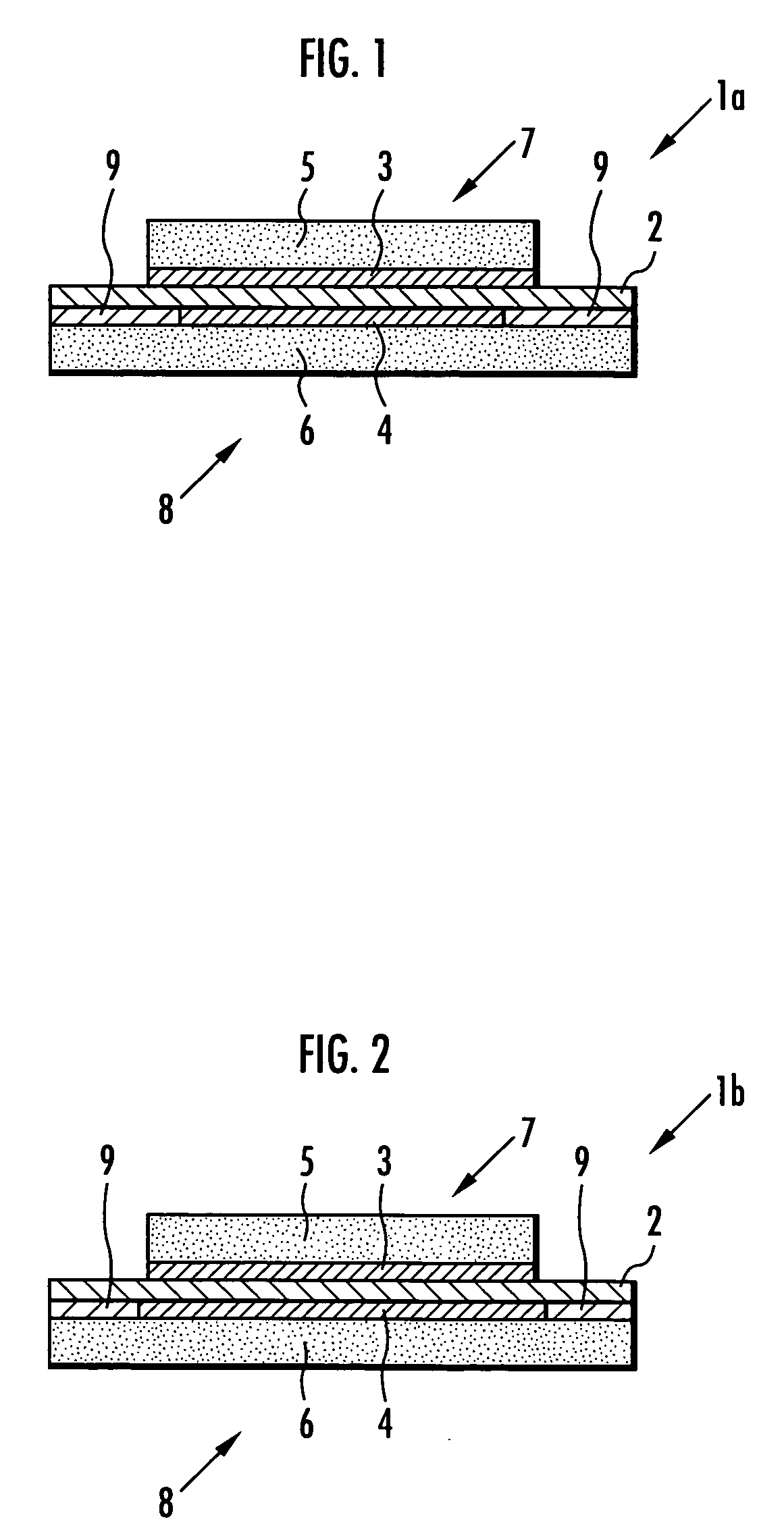
[0016] According to the membrane-electrode structure of the present invention, since the adhesive support layer is formed of an adhesive having fluorine atoms in the molecular structure, it can strongly adhere to the solid polymer electrode membrane and does not peel off, even if it is exposed to a high-temperature high-humidity environment during the operation of the fuel cell. Therefore, it can protect the solid polymer electrolyte membrane extended outwardly from the outer circumferential edges of the catalyst layers and can prevent the damage thereof. The adhesive support layer may be formed on only one face of the solid polymer electrolyte membrane or may be formed on both faces thereof.
[0018] According to the adhesive support layer formed of such an adhesive, since the adhesive has a tensile elongation at break of 150% or more, the adhesive support layer can follow the expansion and shrinkage of the solid polymer electrolyte membrane in the high-temperature high-humidity environment, and can relax the concentration of stress of the solid polymer electrolyte membrane in the edge portion thereof to prevent damage.
[0021] The membrane-electrode structure of the present invention is characterized in comprising a diffusion layer that coats the catalyst layers and the adhesive support layer. The catalyst layers and the adhesive support layer are reinforced by the coating of the catalyst layers and the adhesive support layer by the diffusion layer, and the solid polymer electrolyte membrane extended outwardly from the outer circumferential edge of the catalyst layers is further strongly protected.
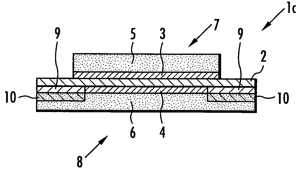
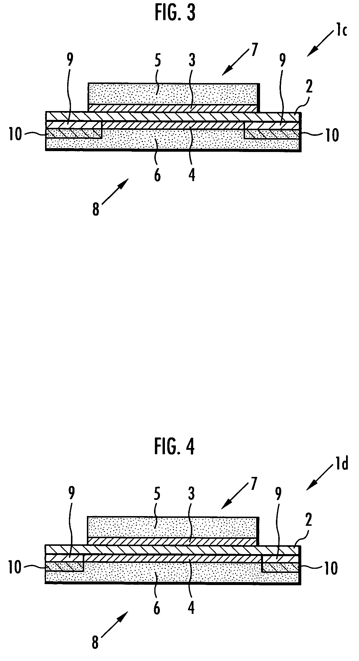
[0023] Therefore, the membrane-electrode structure of the present invention is characterized in that the diffusion layer is formed of a porous material, and the adhesive support layer is integrated with the diffusion layer through an adhesive permeating layer wherein the adhesive permeates in the diffusion layer. In the membrane-electrode structure of the above constitution, the adhesive support layer formed on at least one face of the solid polymer electrolyte membrane is integrated with the diffusion layer that coats the adhesive support layer through the adhesive permeating layer. Therefore, the strength of the diffusion layer is improved, and when a fuel cell is constituted by laminating a plurality of the membrane-electrode structures on each other, the plastic deformation or damage of the diffusion layer can be prevented.
[0028] Therefore, the membrane-electrode structure of the present invention is characterized in that at least a part of the outer circumferential edge of one catalyst layer positions at the portion different from the outer circumferential edge of the other catalyst layer, with sandwiching the solid polymer electrolyte membrane. According to the above-described constitution, the stress due to outer circumferential edges of the catalyst layers can be dissipated on both the front and back of the solid polymer electrolyte membrane, and the damage of the solid polymer electrolyte membrane can be prevented.
[0032] According to the producing method of the present invention, in the solid polymer electrolyte membrane, irregularity having a maximum height Rmax of surface roughness within a range between 3 and 20 μm is previously formed on the area of the solid polymer electrolyte membrane coated by the adhesive support layer, and the adhesive support layer is bonded to the area where the irregularity of the solid polymer electrolyte membrane has been formed by pressing under heating. As a result, a strong adhesive force can be obtained between the adhesive support layer and the solid polymer electrolyte membrane having the irregularity, and the adhesive support layer does not peel off even if it is exposed to a high-temperature high-humidity environment during the operation of the fuel cell. Therefore, the solid polymer electrolyte membrane extended outwardly from the outer circumferential edges of the catalyst layers is protected by the adhesive support layer, and the damage thereof can be prevented.

Problems solved by technology

The petroleum source has been exhausted, and at the same time, environmental problems such as global warming due to the consumption of fossil fuel have increasingly become serious.
However, as FIG. 8 shows, if the catalyst layers 3 and 4 and the diffusion layers 5 and 6 are laminated so that the outer circumferential edges thereof are aligned with the outer circumferential edge of the polymer electrolyte membrane 2, there is a problem that the gas supplied to each of the diffusion layers 5 and 6 goes around the outer circumferential edge of the polymer electrolyte membrane 2 to the opposite side, and is mixed to each other.
In addition, since the locations of the outer circumferential edges of the catalyst layers 3 and 4 are close to each other, there is a problem that the catalyst layers 3 and 4 may be electrically short-circuited.
However, since a fuel cell is exposed to a high-temperature high-humidity environment during operation, the adhesive support layer 9 may peel off the polymer electrolyte membrane 2 depending on the type of adhesive that constitutes the adhesive support layer 9 of the membrane-electrode structures 1a and 1b, and the effect to protect the polymer electrolyte membrane 2 may not be sufficiently achieved.

Method used


Image

  • Membrane-electrode structure and method for producing the same
  • Membrane-electrode structure and method for producing the same
  • Membrane-electrode structure and method for producing the same

Examples


example 1

[0071] In this example, an adhesive was first prepared by mixing and agitating 100 parts by weight of the polymer represented by the following formula (1) (viscosity: 4.4 Pas; average molecular weight: 16,500; quantity of vinyl groups: 0.012 mol / 100 g); 4 parts by weight of organo-hydrogen polysiloxane (CR-100 (trade name) manufactured by Kaneka Corporation); 8 parts by weight of a plasticizer (PAO-5010 (trade name) manufactured by Idemitsu Petrochemical Co., Ltd.); 12 parts by weight of fumed silica (manufactured by Tosoh Silica Corporation); and 3 parts by weight of organo-silane (KBM-303 (trade name) manufactured by Shin-Etsu Chemical Co., Ltd.); defoaming; and adding a xylene solution (8.3×10⁻⁵ mol / μl) of bis(1,3-divinyl-1,1,3,3-tetramethyl disiloxane)-platinum catalyst as a reaction catalyst so that the content of platinum is 5×10⁻⁴ equivalent weights to the number of moles of the vinyl groups in the polymer represented by the following formula (1).

[0072] The tensile elongati...

example 2

[0099] In this example, an adhesive was prepared in the same manner as in Example 1 except that the quantity of compounded fumed silica was 20 parts by weight. The tensile elongation at break after curing of the above adhesive measured in the same manner as in Example 1 was 150%.

[0100] Next, a membrane-electrode structure 1a shown in FIG. 1 and a membrane-electrode structure 11a shown in FIG. 5 were produced in the same manner as in Example 1 except that the adhesive prepared in this example was used in place of the adhesive used in Example 1, and the stress concentration of the solid polymer electrolyte membrane 2 was examined in the same manner as in Example 1. The results are shown in Table 2.

example 3

[0101] In this example, an adhesive was produced by mixing and agitating 100 parts by weight of methyl (3,3,3-trifluoropropyl) polysiloxane of which both ends of the molecular chain are blocked by dimethylvinylsiloxy groups (viscosity: 1.0 Pa·s; content of vinyl groups bonded to silicon atoms: 1.0% by weight); 3.5 parts by weight of dimethylhydrogensiloxy(3,3,3-trifluoropropyl)polysiloxane of which both ends of the molecular chain are blocked by dimethylhydrogensiloxy groups (viscosity: 0.01 Pa-s; content of vinyl groups bonded to silicon atoms: 0.5% by weight); and 0.01 parts by weight of ferrocene; and defoaming; to which a xylene solution (8.3×10⁻⁵ mol / μl) of bis(1,3-divinyl-1,1,3,3-tetramethyl disiloxane)-platinum catalyst was added as a reaction catalyst so that the ratio by weight of platinum to methyl(3,3,3-trifluoropropyl)polysiloxane of which both ends of the molecular chain are blocked by dimethylvinylsiloxy groups was 5 ppm. The tensile elongation at break after curing of...


PUM

PropertyMeasurementUnit
tensile elongation at breakaaaaaaaaaa
surface roughnessaaaaaaaaaa

Abstract

The present invention provides a membrane-electrode structure having an adhesive support layer that does not peel off the solid polymer electrolyte membrane in a high-temperature high-humidity environment during the operation of a fuel cell, and a producing method thereof. The present invention also provides a polymer electrolyte fuel cell that uses the membrane-electrode structure, and an electric apparatus and a transport apparatus that use the polymer electrolyte fuel cell. The solid polymer electrolyte membrane 2 is sandwiched by catalyst layers 3 and 4 positioned in the inner circumferential side thereof, and one face is coated with the catalyst layers 3 and 4 and the adhesive support layer 9. The adhesive support layer 9 is formed of an adhesive that has fluorine atoms in the molecular structure. The adhesive has a tensile elongation at break of 150% or more after curing. Having porous diffusion layers 5 and 6 that coat the catalyst layers 3, 4 and the adhesive support layer 9, the adhesive support layer 9 is integrated with the diffusion layer 6 through adhesive permeating layers 10. Irregularity that has a maximum height Rmax of surface roughness within a range between 3 and 20 μm is formed on the area coated by the adhesive support layer 9 of the solid polymer electrolyte membrane 2, and the adhesive support layer 9 is bonded to the area where the irregularity has been formed by pressing under heating.

Description

TECHNICAL FIELD [0001] The present invention relates to a membrane-electrode structure that is used in polymer electrolyte fuel cells, and a method for producing the same. BACKGROUND ART [0002] The petroleum source has been exhausted, and at the same time, environmental problems such as global warming due to the consumption of fossil fuel have increasingly become serious. Thus, a fuel cell receives attention as a clean power source for electric motors that is not accompanied with the generation of carbon dioxide. The above fuel cell has been widely developed, and some fuel cells have become commercially practical. When the above fuel cell is mounted in vehicles and the like, a polymer electrolyte fuel cell comprising a polymer electrolyte membrane is preferably used because it easily provides a high voltage and a large electric current. [0003] A membrane-electrode structure as shown in FIG. 8 has been known as a membrane-electrode structure used for the above polymer electrolyte fue...

Claims


Application Information

Patent Timeline
Patent Type & Authority Applications(United States)
IPC IPC(8): B05D5/12H01M2/08H01M4/86H01M8/00H01M8/02H01M8/10
CPCH01M8/0284H01M8/1004Y02E60/521H01M2300/0082H01M2008/1095Y02E60/50
Inventor MITSUTA, NAOKISHINKAI, HIROSHINANAUMI, MASAAKI
Owner HONDA MOTOR CO LTD
Learn More