
Method of producing target material of Mo alloy

a target material and mo alloy technology, applied in the direction of vacuum evaporation coating, coating, transportation and packaging, etc., can solve the problems of particle content in deposited films, and a high risk of additive element segregation, so as to reduce the unfavorable shape-change of pressurized and sintered bodies, reduce the segregation of material components, and improve the packaging density of raw material powder blends

Inactive Publication Date: 2005-09-01
HITACHI METALS LTD
View PDF1 Cites 68 Cited by
  • Summary
  • Abstract
  • Description
  • Claims
  • Application Information

AI Technical Summary

Benefits of technology

[0007] An object of the present invention is to provide a method of producing a target material of a Mo alloy, according to which method a packing density of a raw material powder in a container for pressurizing is improved, an unfavorable shape-change of a pressurized and sintered body is reduced, and a segregation of material components is decreased.
[0021] According to the present invention, it is possible to achieve the above object that a packing density of a raw material powder blend in a container for pressurizing is improved, an unfavorable shape-change of a pressurized and sintered body is reduced, and a segregation of material components is decreased.

Problems solved by technology

However, according to such a method of using the number of bonded raw target material sections, there arises a problem of particles contained in a deposited film due to abnormal spatters of the material which are generated during sputtering process because of a clearance existing between the respective adjacent bonded raw target material sections.
However, even by the method of producing a Mo or Mo alloy target material disclosed in the above patent publications, when producing the target material of a Mo alloy containing an additive element(s), there arises a problem that a segregation of the additive element(s) is liable to occur, which problem cannot be solved by the above method.
In addition, there arises also a problem of an unfavorable shape-change of a pressurized and sintered body.

Method used


Image

  • Method of producing target material of Mo alloy
  • Method of producing target material of Mo alloy
  • Method of producing target material of Mo alloy

Examples


example 1

[0051] There were prepared a Mo powder having an average particle size of 12 μm, a W (tungsten) powder having an average particle size of 12 μm, a Nb powder having an average particle size of 100 μm, a Ti powder having an average particle size of 100 μm, and a Zr powder having an average particle size of 100 μm.

[0052] Specimen Nos. 1 to 6 target materials shown in Table 1 were produced by the following process, which are of the present invention.

[0053] (1) In order to produce each of the specimens, given amounts in atomic % of the Mo powder and any one of the transition metal powder were checkweighed.

[0054] (2) The checkweighed powders were blended for 10 minutes with utilization of a V-type blender to obtain a raw material powder.

[0055] (3) The raw material powder was compressed under pressure of 265 MPa by a CIP machine to form a green compact.

[0056] (4) The green compact was pulverized with utilization of a jaw crusher and a disc mill to produce a secondary powder.

[0057] (5...

example 2

[0079] A sintered body, having the same chemical composition and the same size as those of Invention Specimen No. 2 shown in Example 1, was produced by the same manner as the case of Invention Specimen No. 2, and after the HIP process it is subjected to hot rolling thrice together with a container for pressurizing under conditions of a temperature of 1150° C. and a reduction ratio of not more than 50%. An expected size of a target material is of a width of 1500 mm and a length of 1800 mm. A result of rolling of the sintered body is shown in Table 2.

TABLE 2DimensionofObjectiveHeatingFirst timeSecond timeThird timeChemicalSintereddimensiontemper-Total rollingrollingrollingrollingSpecimencompositionbodyin rollingaturereductionreductionreductionreductionNo.(atomic %)(mm)(mm)(° C.)(%)(%)(%)(%)Result2-195.0Mo—81 × 812 ×25.7 × 1500 ×115068203043.5No cracking5.0Nb10531800

[0080] As will be seen from Table 2, by carrying out the rolling under conditions of a heating temperature of 500 to 15...

example 3

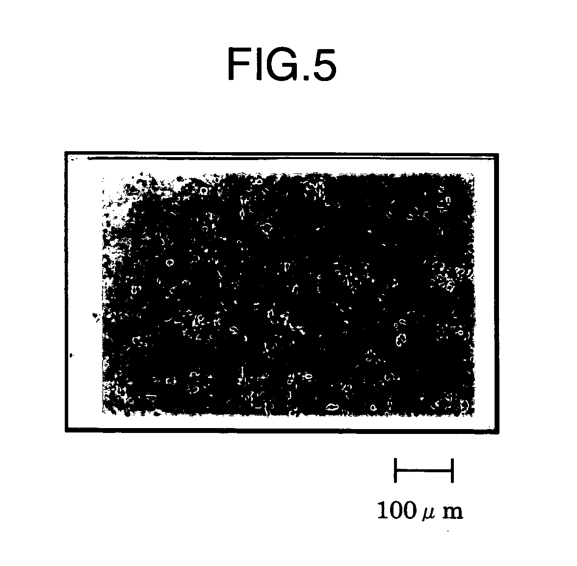
[0082] The target material as hot-rolled in Example 2 was subjected to a recrystallization heat treatment in vacuum at temperatures of 900° C., 1150° C. and 1300° C., respectively. After the work is heated up to a heat treatment temperature, the temperature is held for one hour, and thereafter the work is cooled. Specimen Nos. 2-1-1 , 2-1-2 and 2-1-3 were taken from the three type works, respectively. Microstructures of the specimens were compared with one another with utilization an optical microscope with magnification of 100. The observation result is shown in Table 3. With regard to the specimens subjected to a recrystallization heat treatment at temperatures of 900° C. and 1300° C., respectively, there are provided photographs showing microstructures of the specimens with utilization of an optical microscope with magnification of 100 in FIGS. 4 and 5, respectively.

TABLE 3RecrystallizationChemicalheat treatmentSpecimencompositiontemperatureNo.(atomic %)(° C.)Microstructure2-1-...


PUM

PropertyMeasurementUnit
Temperatureaaaaaaaaaa
Lengthaaaaaaaaaa

Abstract

Disclosed is a method of producing a target material of a Mo alloy, which includes the steps of (a) preparing a green compact by compressing a raw material powder blend consisting of a Mo powder having an average particle size of not more than 20 μm and a transition metal powder having an average particle size of not more than 500 μm; (b) pulverizing the green compact to produce a secondary powder having an average particle size of from not less than an average particle size of the raw material powder blend to not more than 10 mm; (c) filling the secondary powder into a container for pressurizing; and (d) subjecting the secondary powder with the container for pressurizing to sintering under pressure thereby obtaining a sintered body of the target material.

Description

BACKGROUND OF THE INVENTION [0001] The present invention relates to a method of producing a target material of a Mo alloy by a powder sintering method. [0002] At present, a film of a refractory metal such as Mo having low electric resistance is used for a thin film electrode, thin film wiring and so on in a liquid crystal display (hereinafter referred to as LCD), which thin metal film is generally formed from a target material for sputtering. In recent years, there is a trend toward larger size LCDs which accompany a demand for a larger size of the target material, particularly, a long size article having a length of not less than 1 m or a large size article having a sputtering area of more than 1 m2. [0003] Conventionally, in response to the trend toward a larger size of the sputtering area, there have been proposed several ways including a method of bonding a number of raw target material sections to a backing plate. However, according to such a method of using the number of bonde...

Claims


Application Information

Patent Timeline
IPC IPC(8): B22F3/15B22F3/04B22F3/12B22F3/16B22F3/24C22C1/04C23C14/34
CPCB22F3/1208B22F3/162B22F2003/248B22F2998/00B22F2998/10C22C1/045C23C14/3414B22F5/003B22F1/0003B22F1/0096B22F3/15B22F1/09B22F1/148
Inventor IWASAKI, KATSUNORIINOUE, KEISUKEUEMURA, NORIO
Owner HITACHI METALS LTD
Learn More