
Porous ceramic filters with catalyst coatings

a technology of ceramic substrates and catalysts, applied in catalyst activation/preparation, metal/metal-oxide/metal-hydroxide catalysts, chemical/physical processes, etc., can solve the problems of increasing thermal expansion, reducing gas permeability, and the problem is the most severe, so as to reduce pressure drop, reduce pressure drop, and extensive cross-linking of polymers

Active Publication Date: 2005-09-01
CORNING INC
View PDF5 Cites 53 Cited by
  • Summary
  • Abstract
  • Description
  • Claims
  • Application Information

AI Technical Summary

Benefits of technology

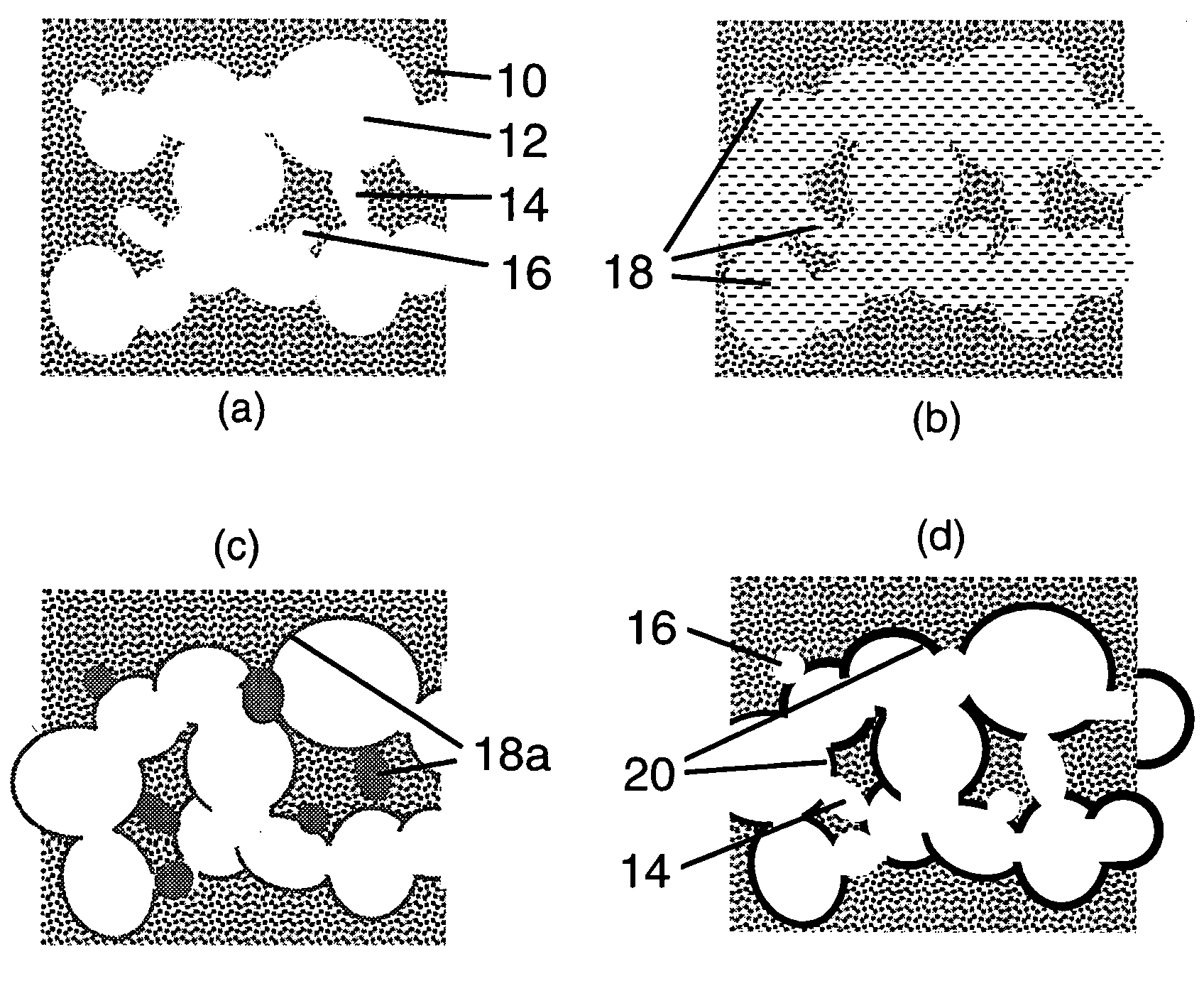
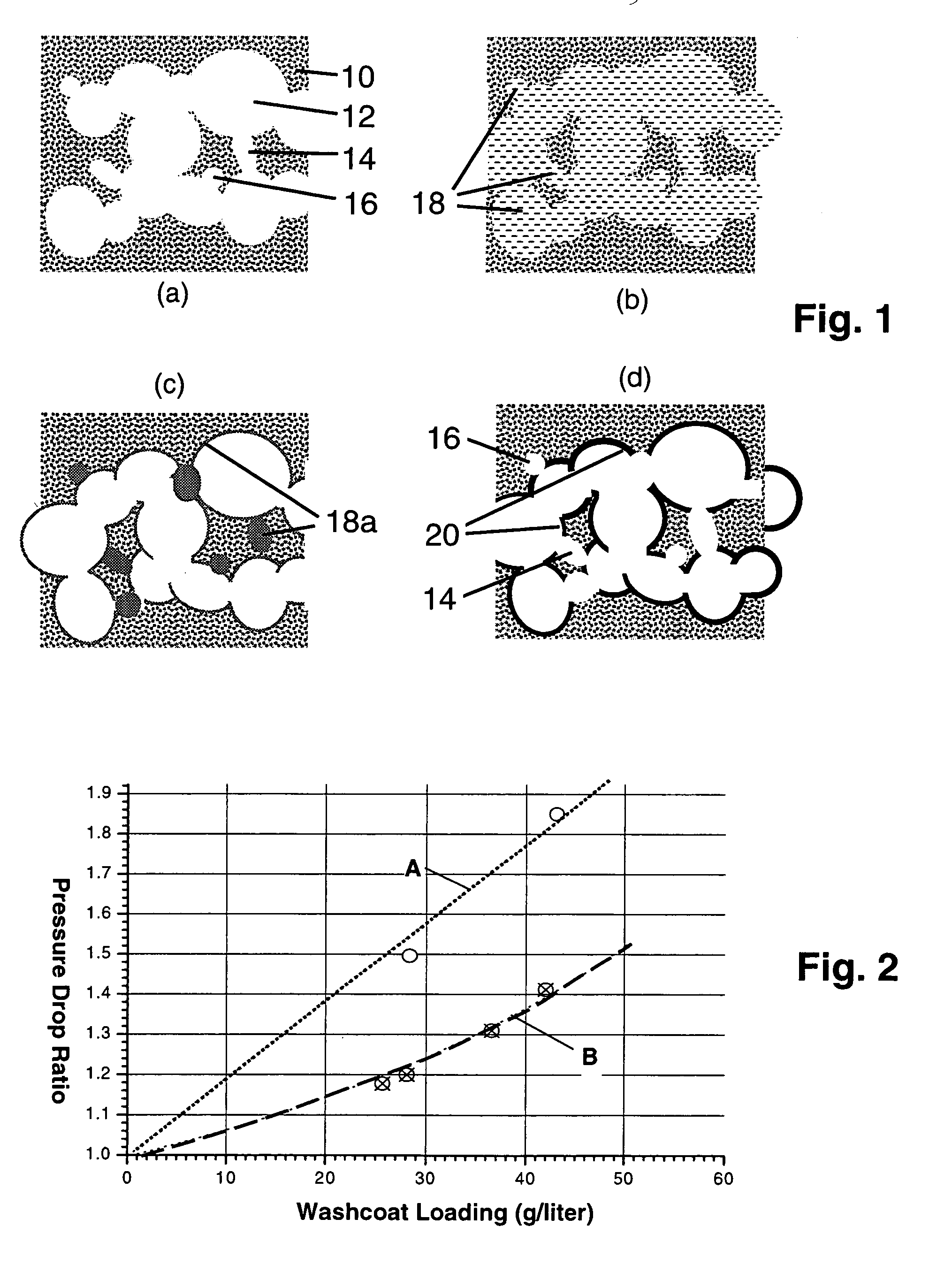
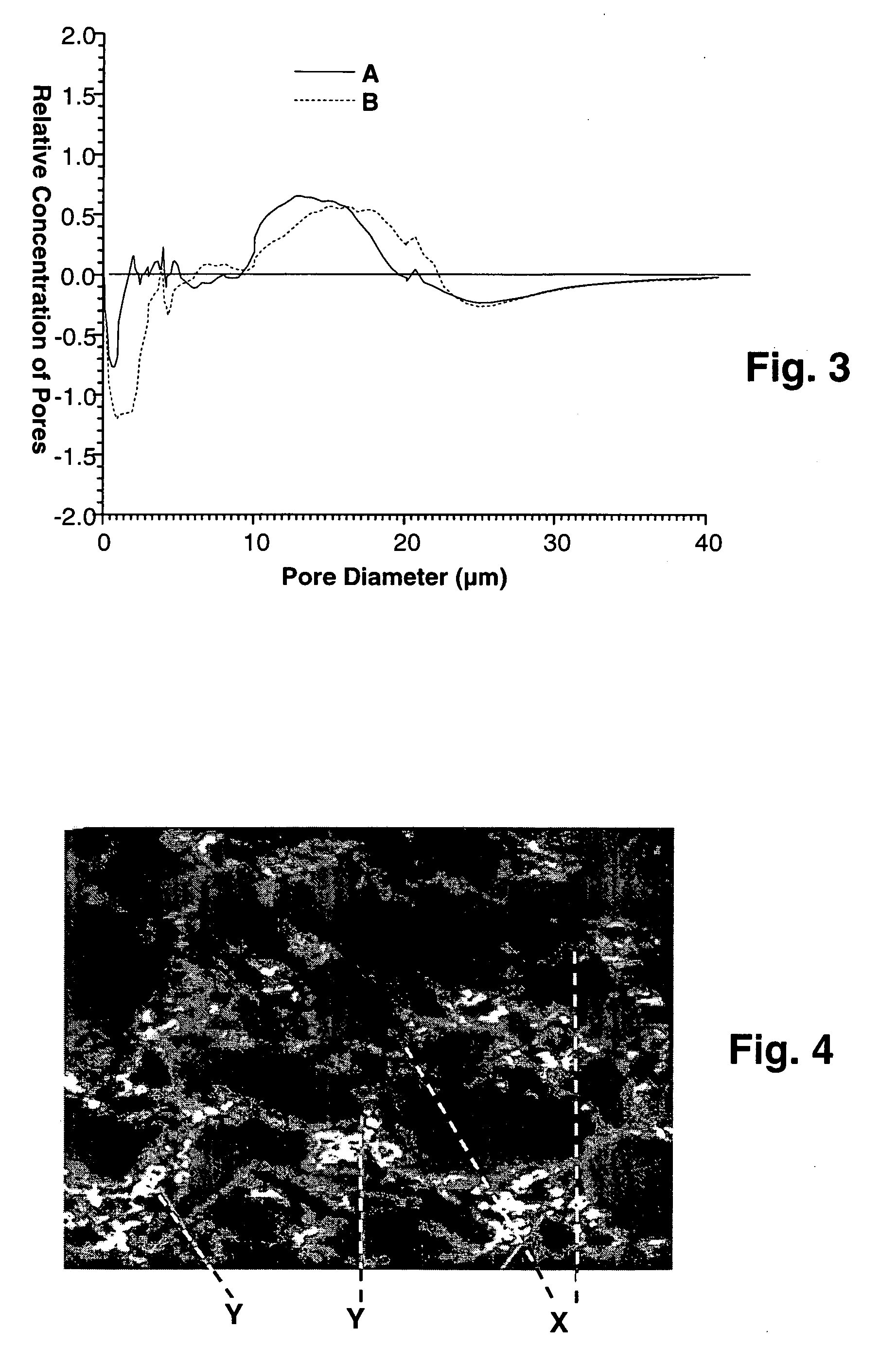
The present invention provides improved methods for passivating high porosity ceramic honeycomb filters with washcoats and catalyst coatings. The methods selectively protect or pre-fill microcracks, micropores, and microchannels during the washcoating process, thus better protecting the gas permeability of the filter walls. The methods involve applying a thermally cross-linked polymer solution or dispersion to the ceramic support or filter structure, followed by heating to remove the polymer coating and restore gas flow. The resulting catalyst-coated or washcoated support has lower pressure drop and is particularly well-adapted for use as a filter to remove particulate material from fluid streams such as combustion exhaust gases. The selective nature of the polymer coating also reduces the amount of polymer needed and secondary emissions during the catalyst coating process.

Problems solved by technology

However, one difficulty encountered with porous ceramics intended to function as particulate filters is the tendency to decrease in gas permeability and increase in thermal expansion as catalysts and catalyst support washcoatings are applied to the filter walls.
The problem is most severe in the case of highly microcracked ceramics such as the aluminum titanates, particularly when the washcoating formulations contain materials of very fine particle size (e.g., particle diameters in the 0.02-0.1 μm range).
Microcracking is a significant contributor to the low CTEs exhibited by many of these materials, with crack closure during heating considerably moderating the dimensional increases that would otherwise occur.
At these CTE levels the risk of structural damage to the filters under the normal conditions of exhaust filter use is unacceptable.

Method used


Image

  • Porous ceramic filters with catalyst coatings
  • Porous ceramic filters with catalyst coatings
  • Porous ceramic filters with catalyst coatings

Examples


example 1

[0039] Cross-linkable polymer solutions are prepared following one of two procedures. In a first procedure, 4.0 g of 70% (weight) hexamethylenediamine solution and 7.5 g of 99% (weight) epichlorohydrin are mixed into 2500 ml samples of three ionene polymer solutions. The polymer solutions are solutions of 1.5% (weight), 3% (weight), and 6% (weight) polymer concentration, being made up in each case by an appropriate water dilution of a commercial ionene polymer preparation. The commercial preparation is PC-1195™ polymer solution, sold by GE Betz, GE Water Technologies, Trevose, Pa., U.S.A. and containing about 40-50% by weight of dissolved amine-functional ionene polymer solids having a molecular weight of about 170,000. The three cross-linkable polymer solutions thus provided are allowed to age for five days prior to use.

[0040] In a second procedure, a 3450 ml sample of a 12% (weight) PC-1195™ ionene solution is mixed with 30.0 g of a 70% (weight) hexamethylenediamine solution and ...

example 2

[0048] Following the procedure of Example 1 above, several additional aluminum titanate ceramic samples similar in composition to the filter samples of Example 1, but having a lower average linear coefficient of thermal expansion (CTE) of about 4.7×10⁻⁷ / ° C. over the 25-1000° C. temperature range, are polymer-coated and washcoated as described in that Example. The washcoated samples are then tested for the extent of CTE increase, with the results reported in Table 2 below.

TABLE 2Barrier-Coated Aluminum Titanate Honeycomb SamplesCross-BareCrosslinkableLinkedSam-SamplePolymerPolymerWashcoatpleWeightSolutionCoatingWeightCTENo.(g)ConcentrationWeight (%)(g / L)(×10−7 / ° C.)6-133.932 6.0% wt1.0338.98.86-224.506 9.0% wt1.6141.37.96-336.08912.0% wt2.1240.24.8

[0049] As the data reported in Table 2 suggest, ceramic honeycomb samples coated with cross-linkable ionene polymer solutions of increasing concentration show decreasing levels of thermal expansion change resulting from the washcoating p...

example 3

[0051] A number of ceramic coating samples are prepared from a cordierite ceramic honeycomb stock, the samples being alternately plugged at opposite ends to provide small honeycomb filter samples. The cordierite honeycombs have a cell density of about 31 cells / cm2, a channel wall thickness of about 300 micrometers, and an average linear coefficient of thermal expansion (25-1000° C.) of about 8×10⁻⁷ / ° C.

[0052] Each filter sample is coated with a selected cross-linkable ionene polymer coating from one of the ionene polymer solutions above described, and is then heated to remove water and cross-link the polymer as described in Example 1. The samples are then washcoated with the alumina suspension as described in Example 1, except that the commercial Nyacol® AL20 alumina washcoating suspension was first water-diluted to a pH of 3.5 prior to use. Finally the suspension-coated samples are heated to set the washcoat and pyrolize the polymer coating.

[0053] Table 3 below presents data resu...


PUM

PropertyMeasurementUnit
temperatureaaaaaaaaaa
crack widthsaaaaaaaaaa

Abstract

Porous ceramic catalyst supports or filters to be provided with catalyst coatings via oxide washcoating processes are pre-coated with cross-linked polymer barrier layers to prevent washcoat nanoparticle intrusion into the microcracked and / or microporous surfaces of the ceramics, the barrier coatings being formed by thermally cross-linking hydrocarbon polymers that are vaporizable at moderate washcoat stabilization or catalyst activation temperatures and being preferentially

Description

BACKGROUND OF THE INVENTION [0001] The present invention relates to processes for applying catalyst or catalyst support coatings onto ceramic supports. More particularly, the invention relates to methods for coating ceramic substrates with catalyst coatings wherein a pre-coating or passivation step is used to improve the properties of the catalyzed substrates, by reducing catalyst and / or support coating diffusion into the fine pores, microchannels (necks interconnecting individual pores), and microcrack structure of the substrates. [0002] To address tightening diesel engine emissions regulations being adopted in the United States and Europe, recent attention has focused on basic improvements in the design and performance of ceramic wall-flow honeycomb filters for treating diesel exhaust gases. Among other improvements, design changes allowing for the use of catalyst coatings to control hydrocarbon and / or nitrogen oxide emissions are being implemented. The goal is to develop an impro...

Claims


Application Information

Patent Timeline
Patent Type & Authority Applications(United States)
IPC IPC(8): B01D39/20B01J35/04B01J37/00B01J37/02B01J37/08B32B3/26C04B38/00C04B41/52C04B41/89
CPCB01D39/2075Y10T428/24149B01J37/0018B01J37/0217B01J37/082C04B38/0096C04B41/009C04B41/52C04B41/89C04B2111/00793C04B2111/0081B01J35/04C04B35/00C04B38/0064C04B38/067C04B35/195C04B38/0006C04B41/457C04B41/48C04B41/4535C04B41/5031C04B35/46C04B35/478Y10T428/249953B01J35/56B01D39/00C04B38/00C08F20/06
Inventor TAO, TINGHONGWANG, JIANGUO
Owner CORNING INC
Learn More