
Catheter for inserting into a vessel

a catheter and catheter technology, applied in the field of catheters for insertion into vessels, can solve the problems of multiple invasions, limited ultrasound images, and high cost, and achieve the effect of simple catheter captur

Inactive Publication Date: 2005-09-01
SIEMENS HEALTHCARE GMBH
View PDF16 Cites 75 Cited by
  • Summary
  • Abstract
  • Description
  • Claims
  • Application Information

AI Technical Summary

Benefits of technology

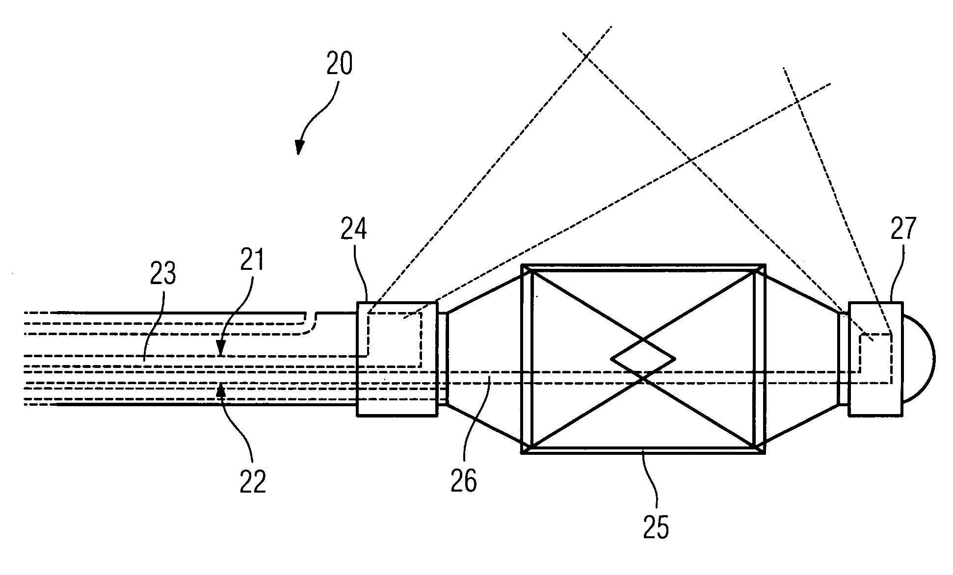
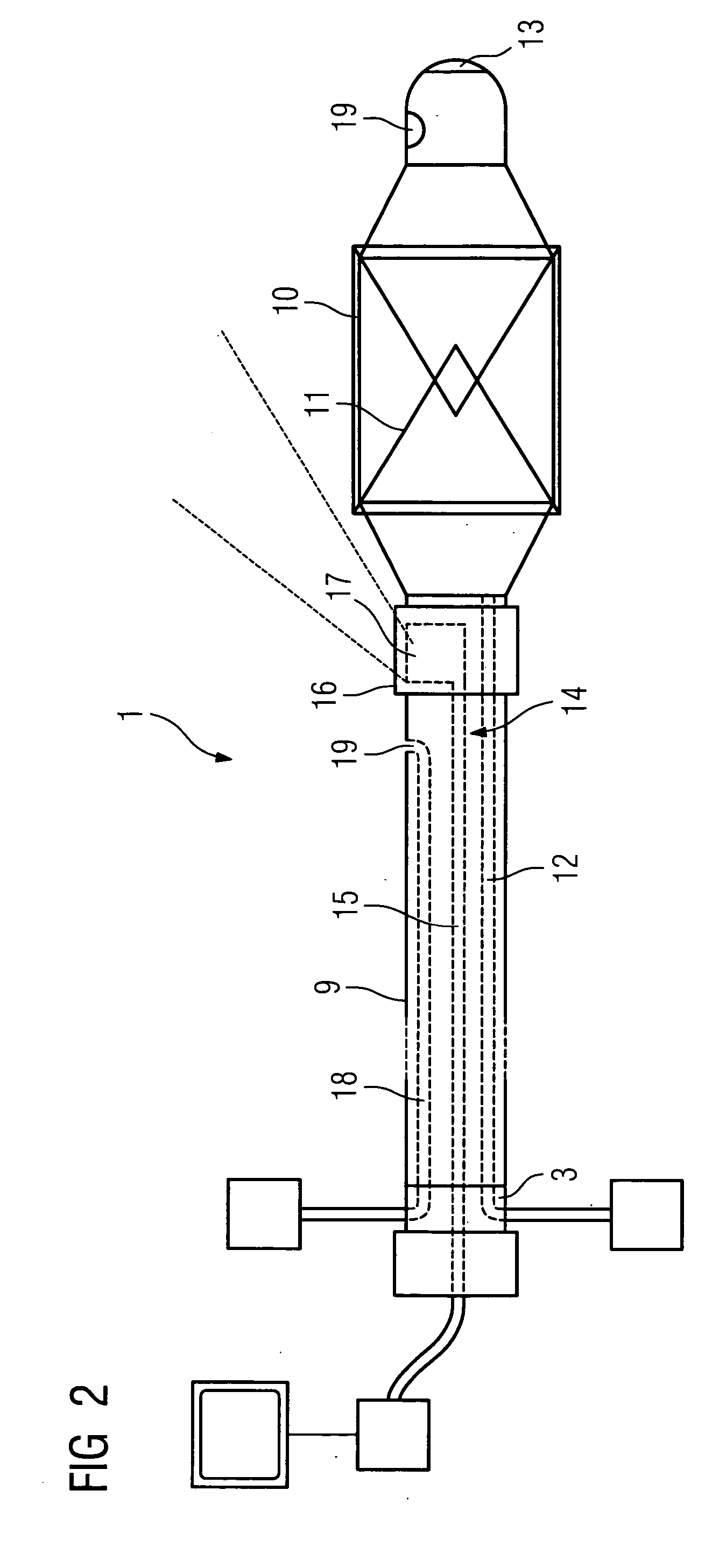
[0010] The OCT imaging device is arranged or configured according to the invention such that it can be used to capture the vessel area, in the vicinity of which the balloon with the stent arranged thereon is located. It is thereby possible particularly advantageously to use the OCT imaging device to verify on the one hand when the vessel area to be treated is reached during the insertion movement, as with continuous OCT imaging movement in the vessel can be detected and monitored continuously. It is also possible to position the balloon and catheter with absolute precision, as the OCT imaging device captures with equal precision the area of the vessel in which the balloon and stent are located. This means that the actual position of the balloon can be detected and the balloon can be positioned precisely. Similarly a location and position control can be carried out continuously during and after the fixing of the stent, without having to move or change the catheter in any way. This means that with a single invasion the catheter according to the invention can provide a precise diagnosis of stenosis and well as accurate orientation and positioning of the stent with simultaneous vessel dilatation. The disadvantages mentioned above are therefore advantageously eliminated, as on the one hand high-resolution images that can be evaluated precisely for diagnosis purposes can be captured using OCT imaging and on the other hand the number of invasions and the number of catheters that have to be used is minimized. In the simplest instance only one catheter, namely the OCT balloon-stent catheter according to the invention, has to be used.
[0015] The stent itself is expediently a so-called drug-eluting stent. With this type of stent, the stent is coated with a drug, which prevents growth in the tissue. Standard uncoated stents are fixed in position in the long term by a growth of vascular tissue around the stent over time once it has been put into position, so that it can be said to grow into place. This is not necessarily desirable, as it is associated with a certain further narrowing of the vessel. This growth is largely prevented when using a drug-eluting stent. Since the growth and scarring of the vessel tissue holding the stent in place are suppressed here, the correct location and positioning of the stent are of particular importance, i.e. the stent has to be fixed in place precisely. This can advantageously be verified with high resolution and precision using ICT imaging.
[0017] In order to link the catheter simply to the external devices required for its operation or to evaluate the information provided, an interface device is expediently provided at its free end. The control and processing device required for optical coherence tomography can be connected to this on the one hand, as can on the other hand a pump used to inflate the balloon, as well as a supply device for fluid to be emitted if required and also if required a control device to generate the magnetic field. Finally one or a plurality of X-ray opaque markings can be provided in the area of the catheter tip, allowing simple capture of the catheter during X-ray angiography.

Problems solved by technology

One disadvantage is that the ultrasound images only have limited, relatively low resolution.
Another disadvantage is that the ultrasound catheter has to be inserted more than once.
It is generally a disadvantage that the known procedure requires multiple invasions.
In other words a number of different catheters have to be inserted, which is disadvantageous, particularly as each invasion is associated with a certain risk to the patient.
However one disadvantage here is particularly the relatively low resolution of the ultrasound images captured by this means, with the result that overall the diagnosis result is no more reliable than with the X-ray angiography used to date and so would not justify the high price for the use of this combination catheter.

Method used


Image

  • Catheter for inserting into a vessel
  • Catheter for inserting into a vessel
  • Catheter for inserting into a vessel

Examples


Embodiment Construction

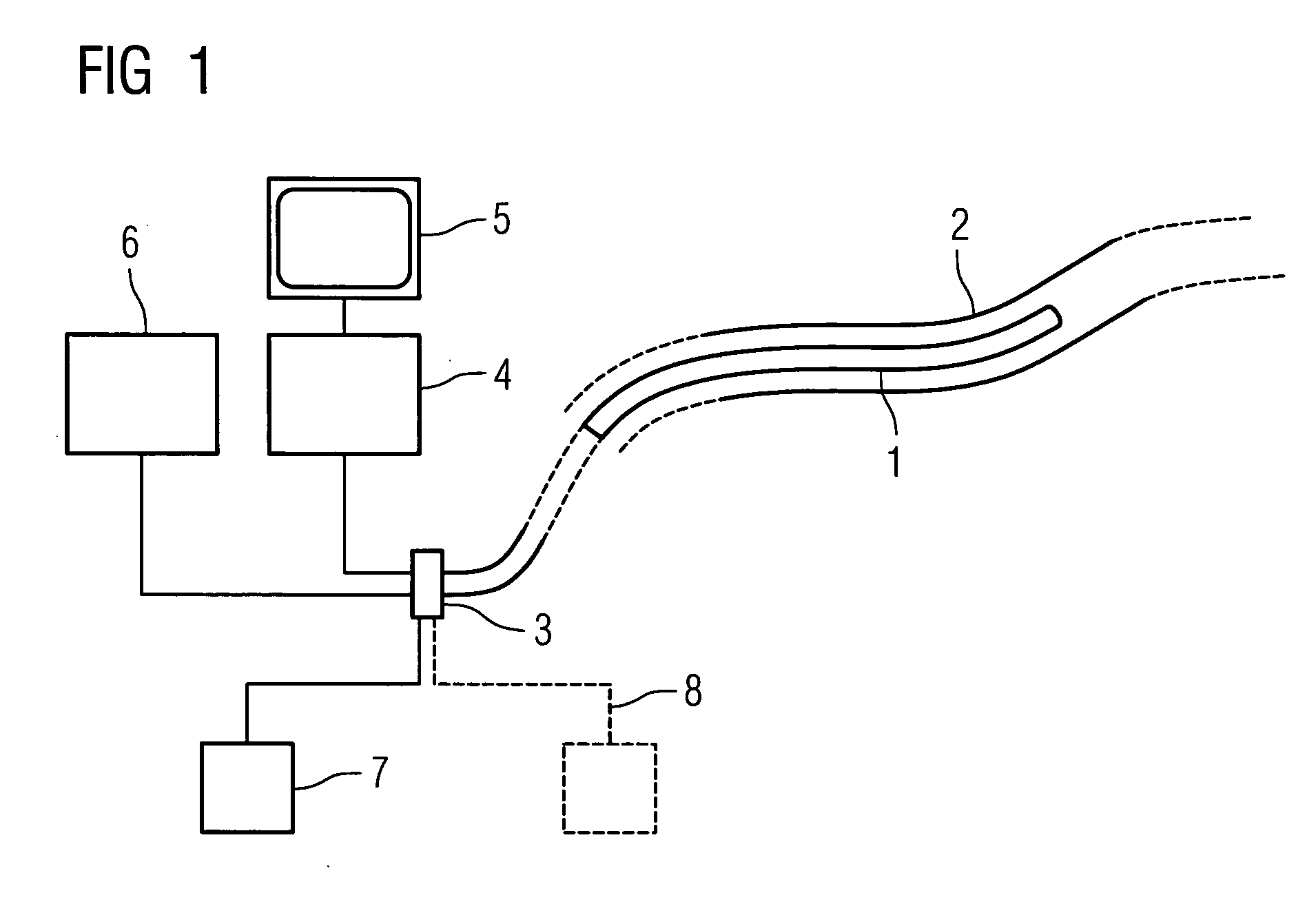
[0022]FIG. 1 shows an outline diagram of a catheter1 according to the invention inserted into a vessel 2. The end of the catheter 1 that is not inserted is connected via an interface device 3 on the one hand to a control and processing device 4 as part of the OCT imaging system. Inside the catheter is an OCT imaging device comprising an optical waveguide, which will be examined in more detail below. Light is supplied via the control and processing device 4 to the integrated optical waveguide and light coming from the optical waveguide is captured and processed, to generate high-resolution OCT images, which are output to a monitor 5.

[0023] Also connected to the interface device 3 is a pump 6, by means of which a balloon provided at the catheter tip, which is used both for dilatation and for widening and positioning the stent, can be inflated.

[0024] Also connected to the interface device 3 is a fluid pump 7, via which rinsing fluid or a contrast agent are fed into the catheter and c...


PUM


Abstract

Catheter for insertion into a vessel, comprising a reversibly inflatable balloon (10, 25) provided in the area of the catheter tip, on the outside of which a stent (11) to be implanted in the vessel is arranged, and at least one imaging device (14, 21, 22) arranged in the area of the catheter tip for optical coherence tomography, which is arranged or configured such that the area of the vessel, in which the balloon (10, 25) is positioned, can be captured.

Description

CROSS REFERENCE TO RELATED APPLICATIONS [0001] This application claims priority to the German application No. 10 2004 001 498.1, filed Jan. 9, 2004 which is incorporated by reference herein in its entirety. FIELD OF INVENTION [0002] The invention relates to a catheter for insertion into a vessel, comprising a reversibly inflatable balloon provided in the area of the catheter tip, a stent to be implanted in the vessel being arranged on the outside of said balloon. BACKGROUND OF INVENTION [0003] One of the most common fatal diseases is vascular disease, in particular cardiac infarct. This is caused by diseases of the coronary arteries, which cause what is known as arteriosclerosis. With such diseases, deposits (atherosclerotic plaque) on the vessel wall cause a reduction in the diameter of the vessel, which can result in the blockage or one or a plurality of coronary arteries. It is now recognized that the risk of cardiac infarct is not primarily due to the reduced vessel diameter. Ra...

Claims


Application Information

Patent Timeline
Patent Type & Authority Applications(United States)
IPC IPC(8): A61B5/00A61F2/958
CPCA61B1/00181A61B5/0066A61F2/958A61B5/6852A61B5/0084
Inventor MASCHKE, MICHAEL
Owner SIEMENS HEALTHCARE GMBH
Learn More