Moving ribbon microphone

Inactive Publication Date: 2005-09-08
AUDIO-TECHNICA
View PDF4 Cites 11 Cited by
  • Summary
  • Abstract
  • Description
  • Claims
  • Application Information

AI Technical Summary

Benefits of technology

[0010] In this configuration, since the surface of the diaphragm, consisting of the aluminum foil, is covered with the gold deposited film, it is possible to improve corrosion resistance to suppress secular variations. Further, the metal deposited film has a high ductility and thus does not affect folding of the diaphragm.
[0011] In a more preferable aspect, the gold deposited film has a thickness of at least 500 Angstrom and 10% or less of the mass of the gold deposited film is added to the diaphragm. This makes it possible to reliably prevent oxidation of the aluminum foil. It is also possible to limit a variation in sensitivity compared to the case in which the

Problems solved by technology

However, the pure aluminum material is prone to couple to moisture in air to form an aluminum hydroxide film on its surface.
The pure aluminum material thus offers only a low corrosion resistance and is disadvantageously susceptible to secular variations.
However, this results in a bimetallic junction with alu

Method used


Image

  • Moving ribbon microphone
  • Moving ribbon microphone

Examples


Example

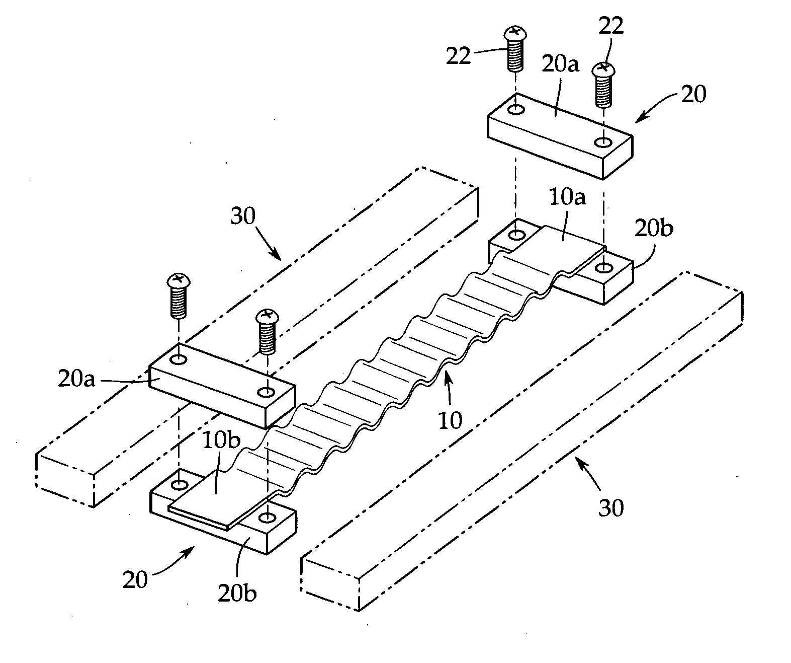
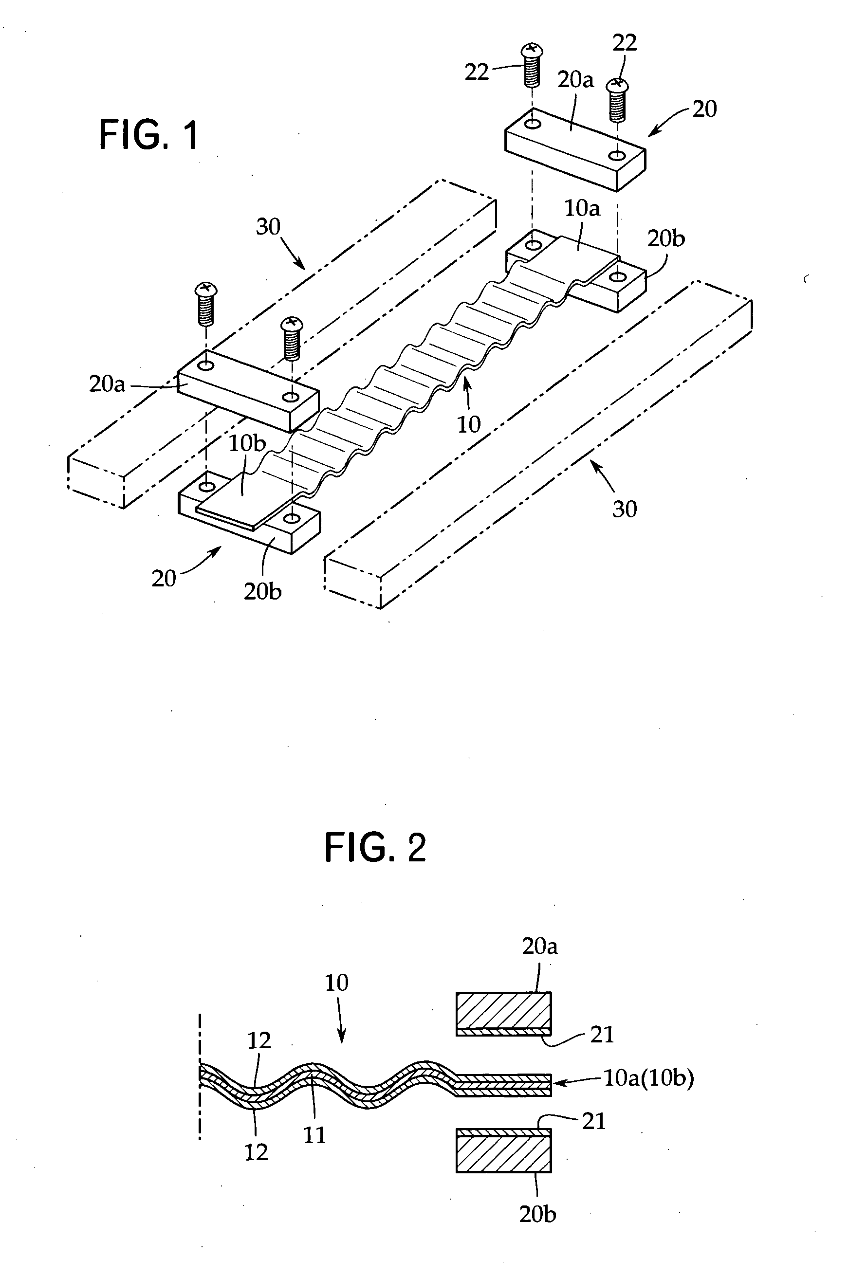
[0015] Now, an embodiment of the present invention will be described with reference to FIGS. 1 and 2. However, the present invention is not limited to this. FIG. 1 is a schematic exploded perspective view showing a moving ribbon microphone. FIG. 2 is an enlarged sectional view showing an essential part of the present invention.

[0016] As shown in FIG. 1, the moving ribbon microphone comprises a diaphragm 10 formed like a ribbon (an elongate band). The diaphragm 10 is folded into a zigzag form except for its opposite ends 10a and 10b in order to reduce resonance frequency. The folding operation can be performed by passing the diaphragm 10 through a molding apparatus having, for example, a pair of gears.

[0017] As shown in the enlarged view in FIG. 2, the diaphragm 10 is composed of an aluminum foil 11 because of its high conductivity, small specific gravity, and ductility that facilitates the folding operation. The aluminum foil 11 is preferably a pure aluminum material, which does n...


PUM


Abstract

The present invention provides a ribbon microphone comprising a diaphragm made of an aluminum foil, in which the aluminum foil offers a corrosion resistance and in which a favorable electrically connected state can be maintained in the junction between the aluminum foil and backplates for a long time. A gold deposited film 12 is formed on opposite surfaces of a diaphragm 10 consisting of a ribbon-like aluminum foil 11. Preferably, a gold deposited film 21 is also formed on inner surfaces of electrode plates 20a and 20b attached to each end 10a (10b) of the diaphragm 10.

Description

TECHNICAL FIELD [0001] The present invention relates to a moving ribbon microphone, and more specifically, to a diaphragm of the microphone which is formed like a ribbon. BACKGROUND ART [0002] A moving ribbon microphone is a velocity microphone in which a ribbon-like diaphragm (ribbon foil) having backplates attached to its opposite ends is placed in a magnetic gap provided by a pair of permanent magnets. Before the advent of a moving coil microphone, Siemens & Halska in Germany developed the first moving ribbon microphone in about 1933 (see Non-Patent Document 1; “50 Years of Audio History” issued by Japan Audio Society on Dec. 4, 1986 (pp. 180 to 187). [0003] In the moving ribbon microphone (simply referred to as a ribbon microphone), the diaphragm is generally composed of an aluminum foil. This is because aluminum is more suitable for the ribbon microphone than other metals in terms of conductivity and specific gravity. [0004] Further, in order to reduce the resonance frequency o...

Claims


Application Information

Patent Timeline
IPC IPC(8): H04R9/08H04R9/00H04R25/00
CPCH04R7/14H04R9/048H04R2307/027H04R9/08
Inventor AKINO, HIROSHI
Owner AUDIO-TECHNICA
Why Eureka
Try Eureka