Scanning miniature optical probes with optical distortion correction and rotational control

a miniature optical probe and rotation control technology, applied in the field of scanning imaging probe design, fabrication and use, can solve the problems of lens not offering the >1 mm depth of field and the >1 mm working distance for many applications, and the current technology is not adequate for meeting, so as to minimize temperature-induced viscosity changes and remove optical effects

Inactive Publication Date: 2005-09-15
LIGHTLAB IMAGING
View PDF17 Cites 195 Cited by
  • Summary
  • Abstract
  • Description
  • Claims
  • Application Information

AI Technical Summary

Benefits of technology

[0008] The invention relates to an optical probe including a sheath; a flexible, bi-directionally rotatable optical transmission system positioned within the sheath; and a viscous damping fluid located in the sheath. The optical transmission system is capable of transmitting, focussing, and collecting light of a predetermined range of wavelengths. The sheath and the viscous damping fluid are transparent to at least some of the wavelengths of that light. The index of refraction of the viscous fluid is typically chosen to remove the optical effects induced by propagation through said sheath. In one embodiment, the optical transmission system is less than substantially 300 μm in diameter. In some embodiments, the sheath is substantially cylindrical. In some embodiments the optical probe further comprises a lumen for providing catheter flushes. In other embodiments, the catheter flushes are maintained substantially at body temperature to minimize temperature induced-viscosity changes in the viscous damping fluid.

Problems solved by technology

Present technology generally is not adequate for meeting the needs of these small probes when the probes must be less than ˜500 μm in diameter, while simultaneously having a working distance that can extend up to several millimeters and performing controlled and potentially complex scan patterns.
Although the design and construction of small lenses is known, as exemplified by a design of a catheter that uses a small (˜1 mm) GRIN lens coupled to a fold mirror for imaging the aperture of a single-mode fiber onto a vessel wall, the scaling of this design to less than 500 μm is problematic.
Although techniques exist for making very small lenses that have small working distances suitable for coupling to laser diodes and other optical components, these lenses generally do not offer the >1 mm working distance and the >1 mm depth-of-field required for many applications.
Presently, such torque wires are not scalable to the sizes required to permit the construction of small optical scanning probes.
Finally, achieving uniform rotational scanning at the distal tip of a single fiber, while maintaining an overall device size less than 500 um in diameter is a major challenge.
Because it is highly undesirable to add a motor to the distal tip, with the attendant wires and size issues, a way must be found to apply torque to the proximal tip and transmit the torque to the distal tip which may be as much as three meters away in a catheter application.

Method used


Image

  • Scanning miniature optical probes with optical distortion correction and rotational control
  • Scanning miniature optical probes with optical distortion correction and rotational control
  • Scanning miniature optical probes with optical distortion correction and rotational control

Examples


Embodiment Construction

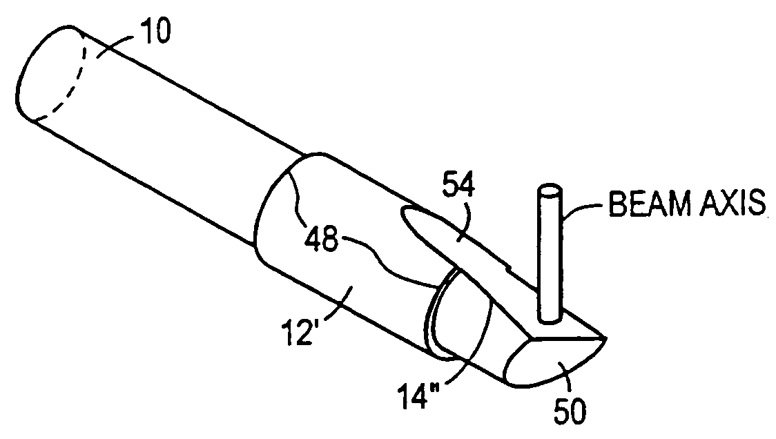
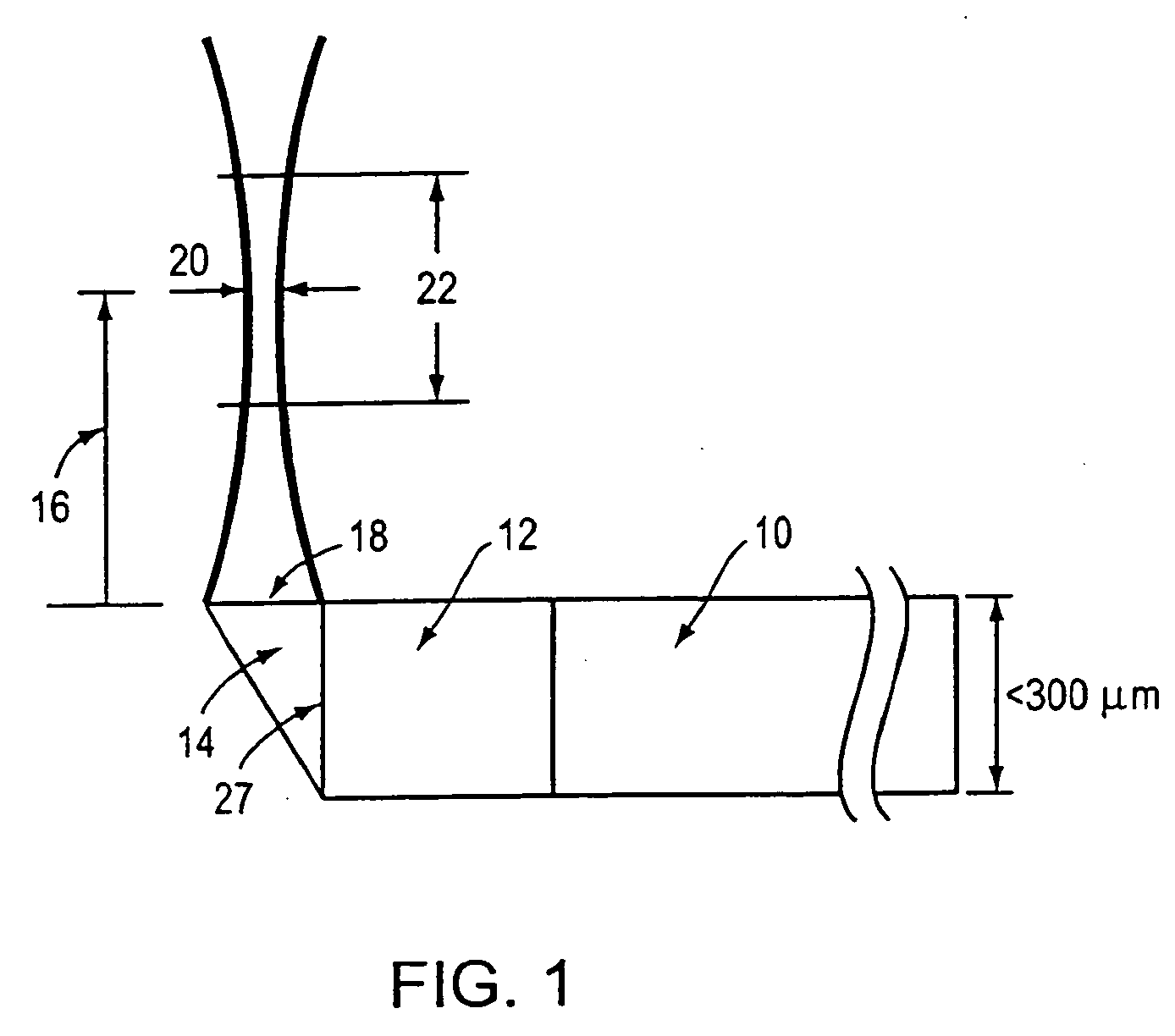
[0025]FIG. 1 shows an example of an embodiment of an imaging lens. In this embodiment a single-mode fiber 10 is spliced or otherwise secured to a lens 12. The lens 12 is approximately the same diameter as the fiber 10. The fiber 10 may include a variety of thin protective coatings. A beam director 14, a 45 (or other suitable angle) degree fold mirror in one embodiment, is affixed to the lens 12 using fusion splicing or glue. The fold mirror 14 is either coated with a high-reflectance material or operates according to the principle of total internal reflection.

[0026] Still referring to FIG. 1, in the embodiment shown, the lens 12 has a working distance 16 from the surface 18 of the fold mirror 14 to the waist location 20 of the Gaussian beam. The combination of the lens 12 and beam director 14 magnify (or reduce) the beam waist originally located at the exit of the single-mode fiber 10 and create a new waist 20 at the spot located at the working distance 16. At the working distance ...


PUM


Abstract

Optical probes having a diameter less than substantially 500 μm for use in scanning light from a long, highly flexible fiber to a sample. In one embodiment the probe includes a viscous damping fluid suitable to prevent non-uniform rotational distortion (NURD).

Description

FIELD OF INVENTION [0001] The field of invention relates to the design, fabrication, and use of ultra-small scanning imaging probes and more particularly to the design and fabrication and use of an ultra-small scanning imaging probes for prevention of rotational distortion. BACKGROUND OF INVENTION [0002] There is a pressing need for developing ultra-small scanning optical probes. These probes require ultra-small imaging lenses and associated scanning and beam director elements. Such probes are used in Optical Coherence Tomography (OCT) and other interferometric imaging and ranging systems, as well as for delivery of other imaging modalities (e.g. fluorescence) or therapeutic optical sources. Future medical (and nonmedical) optical probes will require these miniature probes to navigate small and torturous passageways such as arteries, veins, and pulmonary airways. Present technology generally is not adequate for meeting the needs of these small probes when the probes must be less tha...

Claims


Application Information

Patent Timeline
Patent Type & Authority Applications(United States)
IPC IPC(8): G02B23/26A61B1/00A61B5/00G02B23/24
CPCA61B5/0066A61B5/0084G01B9/02091G02B23/2407G01B9/0205A61B5/6852
Inventor PETERSEN, CHRISTOPHER L.MCNAMARA, EDWARD I.LAMPORT, RONALD B.ATLAS, MICHAELSCHMITT, JOSEPH M.SWANSON, ERIC A.MAGNIN, PAUL
Owner LIGHTLAB IMAGING
Why Eureka
Try Eureka