Low loss optical fiber and method for making same

a technology of low-loss optical fiber and manufacturing method, which is applied in the direction of manufacturing tools, glass deposition burners, instruments, etc., can solve the problems of glass opaqueness and undesirable light transmission, and achieve the effects of low optical loss, high diffusivity, and high diffusion rate of silica glass

Inactive Publication Date: 2005-09-15
CORNING INC
View PDF30 Cites 18 Cited by
  • Summary
  • Abstract
  • Description
  • Claims
  • Application Information

AI Technical Summary

Benefits of technology

[0010] The present invention entails the manufacture of an optical fiber doped with an appropriate material of sufficient purity that low optical loss can be achieved. By low loss we mean an optical attenuation preferably less than about 0.18 dB/km at a wavelength of 1550 nm, more preferably less than about 0.17 dB/km at a wavelength of 1550 nm, and most preferably less than about 0.16 dB/km at a wavelength of 1550 nm. More specifically, the present invention relates to a method for diffusing an alkali metal through a surface of a silica glass article, hereinafter referred to as the diffusion surface, and etching the diffusion surface to a depth sufficient to remove impurities that may have been unintentionally introduced into the glass during the diffusion process. By diffusion surface we mean the surface of the glass article through which diffusion of the alkali metal has occurred. The silica glass article may be in the form of a tube, a rod, or a collection of tubes or rods, or other glass article

Problems solved by technology

If formed within the silica glass article, alkali metal chloride crystals would render the glass opaque and therefore unde

Method used


Image

  • Low loss optical fiber and method for making same
  • Low loss optical fiber and method for making same
  • Low loss optical fiber and method for making same

Examples


example 1

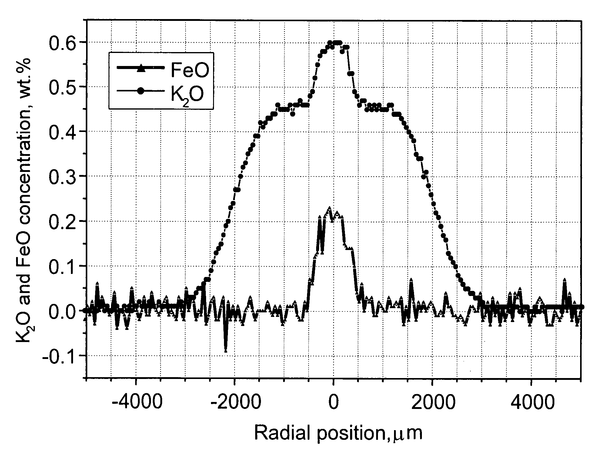
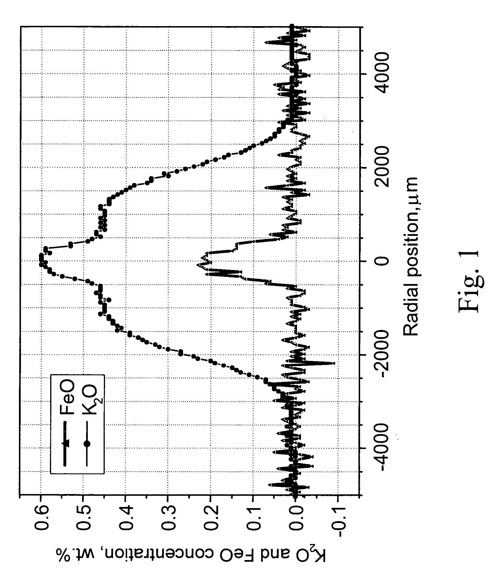
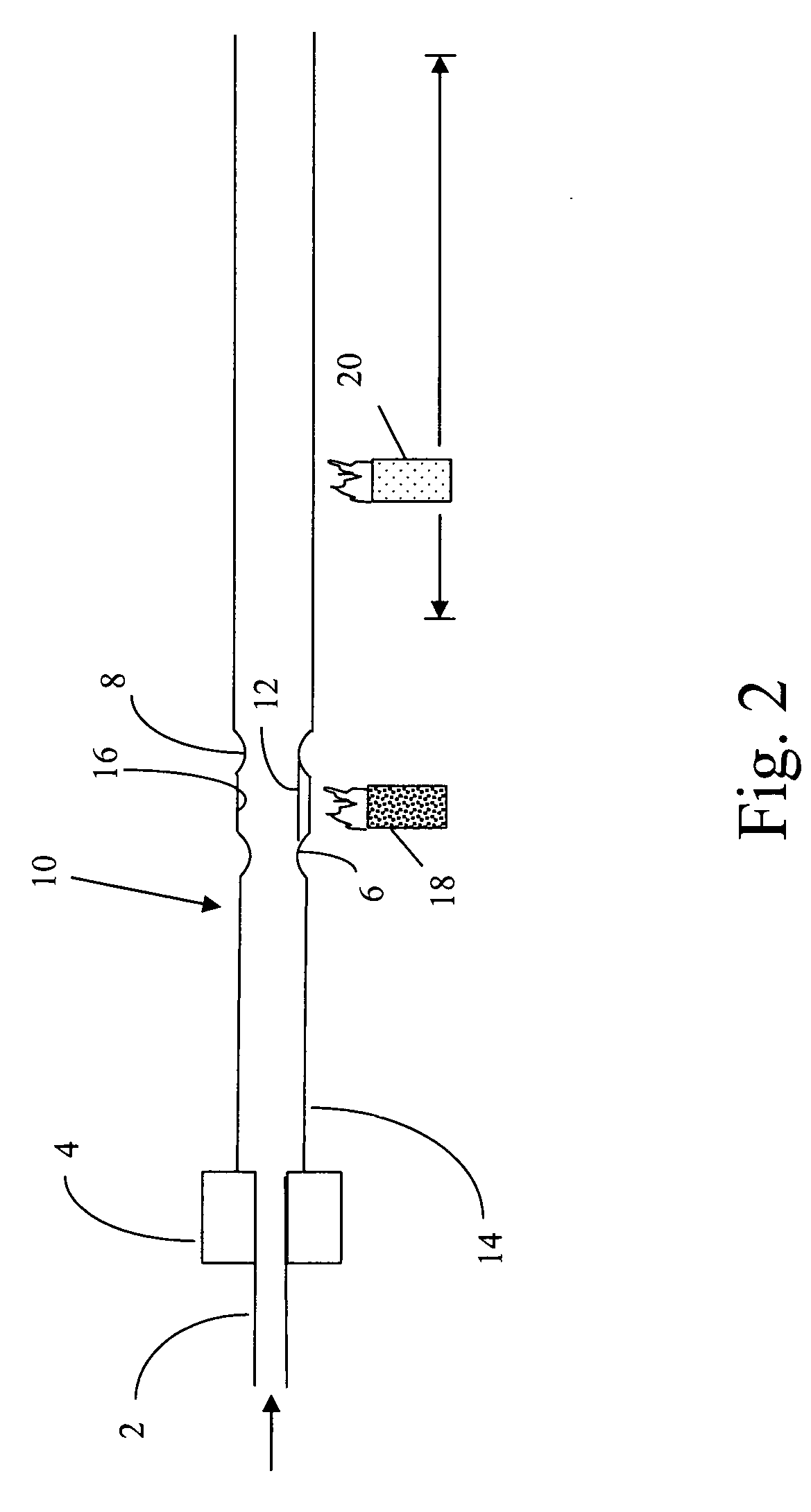
[0029] Referring to FIG. 5, synthetic silica tube 10 having an inside diameter of 19 mm, an outside diameter of 25 mm and about 0.5 m in length, and containing less than 20 ppm Cl, less than 0.05 weight percent F, less than 10 ppb −OH and that is substantially free of transition metal impurities, is mounted in a conventional MCVD glass forming lathe 38 by chuck 36 and chuck 34 at ends 14 and 24 respectively. Oxygen is flowed into inlet 2 and into tube 10 through rotating seal 4 at 2 l / min and a backpressure of 0.75 Torr while tube 10 is simultaneously fire polished at about 2100° C. A reservoir 16 for receiving KBr is formed near end 24 of tube 10 by forging two neck-like deformations, 6 and 8, in the wall of tube 10 about 2 cm from each other. Deformations 6 and 8 are formed by heating tube 10 to its softening point near end 24 with a hand-held torch while tube 10 rotates and pinching the soft glass with pincers common to the glass-blowing arts. End 24 is removed from its respectiv...


PUM

PropertyMeasurementUnit
Fractionaaaaaaaaaa
Fractionaaaaaaaaaa
Fractionaaaaaaaaaa

Abstract

A method of forming an alkali metal oxide-doped optical fiber by diffusing an alkali metal into a surface of a glass article is disclosed. The silica glass article may be in the form of a tube or a rod, or a collection of tubes or rods. The silica glass article containing the alkali metal, and impurities that may have been unintentionally diffused into the glass article, is etched to a depth sufficient to remove the impurities. The silica glass article may be further processed to form a complete optical fiber preform. The preform, when drawn into an optical fiber, exhibits a low attenuation.

Description

[0001] This is a continuation of U.S. patent application Ser. No. 10 / 231,865 filed on Aug. 28, 2002, which is hereby incorporated herein by reference in its entirety, and the benefit of priority is claimed under 35 U.S.C. 120.BACKGROUND OF THE INVENTION FIELD OF THE INVENTION [0002] The present invention relates generally to a method for manufacturing a low loss optical fiber, and more particularly, methods for producing an optical fiber doped with an alkali metal oxide. TECHNICAL BACKGROUND [0003] Attenuation is a principal limiting attribute of optical fibers. Optical fiber loss, for example, plays an important role in setting the limiting distance between optical fiber amplifiers. This is particularly important in long distance and ultra-long distance networks such as, for example, undersea applications, where such amplifiers represent a significant system cost, as well as a major factor in system reliability. Consequently there is a tremendous amount of commercial interest in re...

Claims


Application Information

Patent Timeline
IPC IPC(8): C03B37/00C03B37/012C03B37/014C03B37/018C03C3/06C03C13/04C03C15/00C03C21/00C03C25/60C03C25/68
CPCC03B37/01228G02B6/02C03B37/01861C03B2201/07C03B2201/075C03B2201/20C03B2201/50C03C3/06C03C25/602C03C25/607C03C25/68C03C2201/11C03C2201/23C03C2201/50C03C2203/50C03B37/01211C03B37/01426C03B2203/26C03B2207/30C03B2207/90C03B37/01807C03B37/01892C03B2201/03C03B2201/04C03B2201/12C03B2201/28C03B2201/31C03B2201/32C03B2201/54C03B37/012G02B6/00
Inventor BALL, LAURA J.BANEY, BRUNO P. M.BOOKBINDER, DANA C.HOUSE, KEITH L.KHRAPKO, ROSTISLAV R.MOORE, LISA A.SCHIEFELBEIN, SUSAN L.
Owner CORNING INC
Why Eureka
Try Eureka