Hazardous gas abatement system using electrical heater and water scrubber

Inactive Publication Date: 2005-09-15
INNOVATIVE ENG SOLUTIONS
View PDF30 Cites 12 Cited by
  • Summary
  • Abstract
  • Description
  • Claims
  • Application Information

AI Technical Summary

Benefits of technology

[0008] The present invention is a hazardous gas abatement system for reacting global warming, greenhouse and/or ozone depleting gases using an electrical heater and a water

Problems solved by technology

Existing systems do not provide adequate heating to effectively cleanse exit gas streams of global warming gases.
These previous systems suffered from low efficiency in performance and considerable downtime of equipment during maintenance.
However, the heaters insufficiently heat all of the gases, and the heaters become fouled and unable to efficiently transfer heat.
They also become so burdened

Method used


Image

  • Hazardous gas abatement system using electrical heater and water scrubber
  • Hazardous gas abatement system using electrical heater and water scrubber
  • Hazardous gas abatement system using electrical heater and water scrubber

Examples


Embodiment Construction

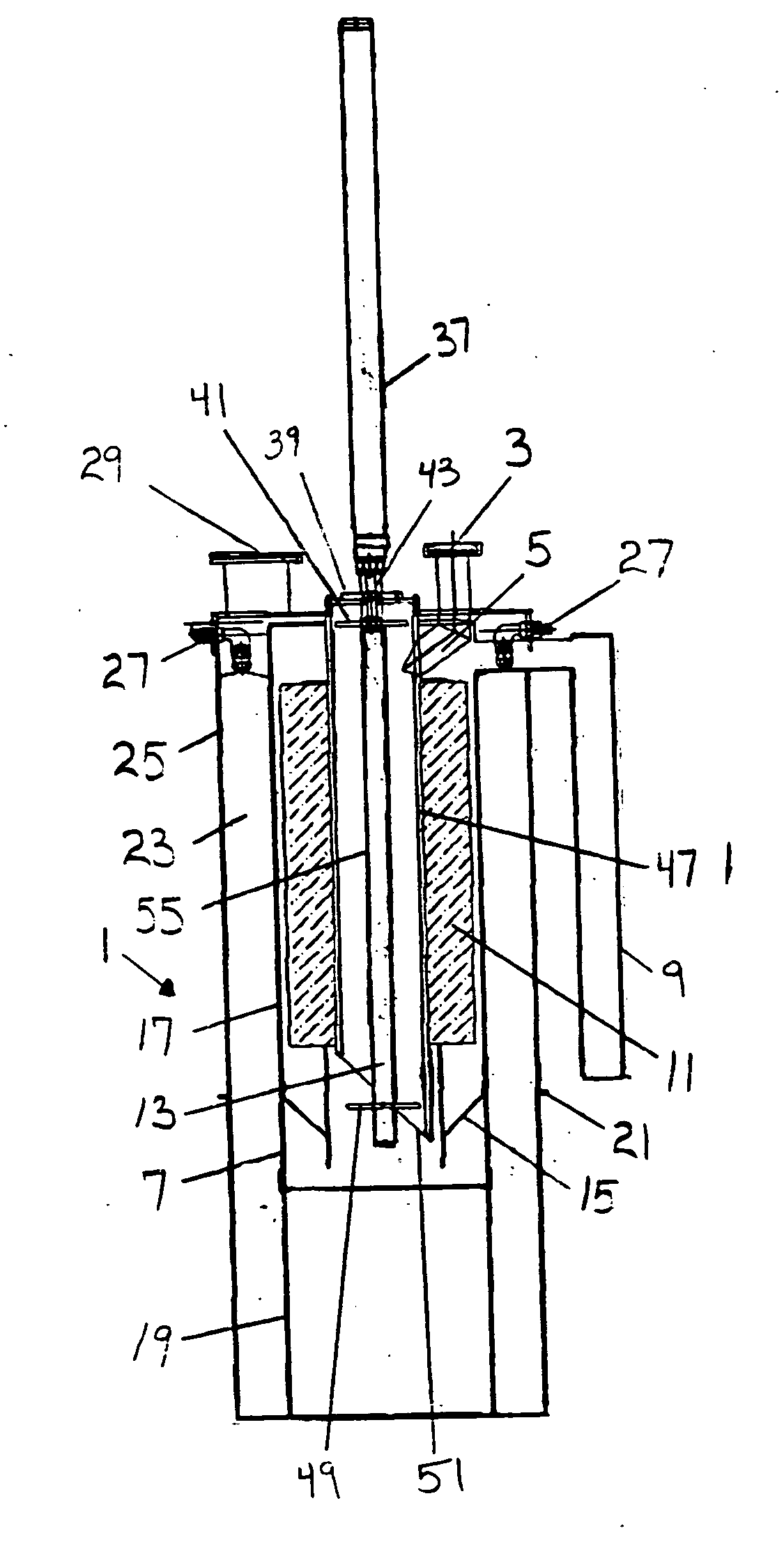
[0020] The present invention is a hazardous gas abatement system for reacting global warming, greenhouse and / or ozone depleting gases using an electrical heater and a water scrubber. The present invention ensures complete or substantially complete neutralization and pacification of any out flowing contaminant gas in the gas stream to be neutralized.

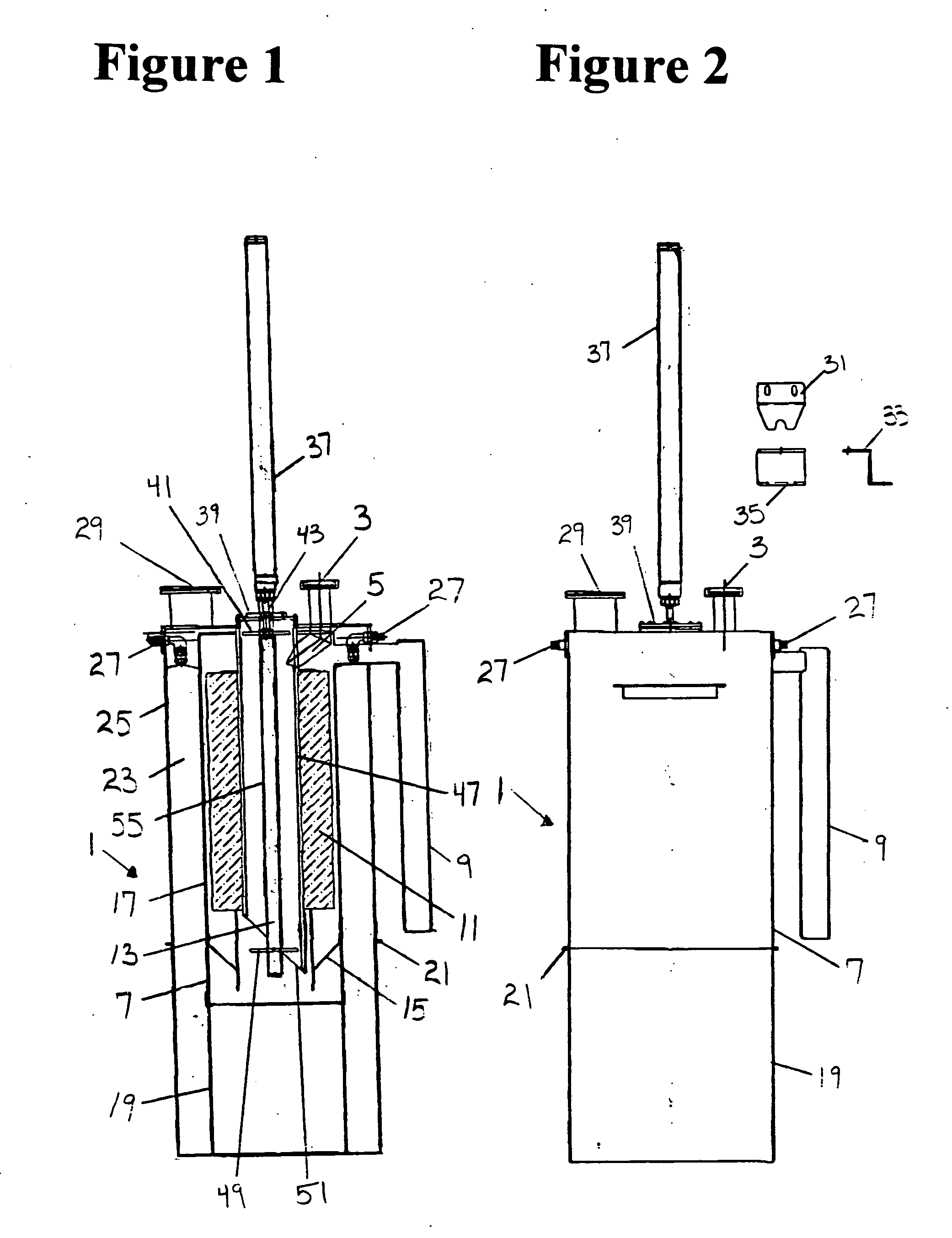
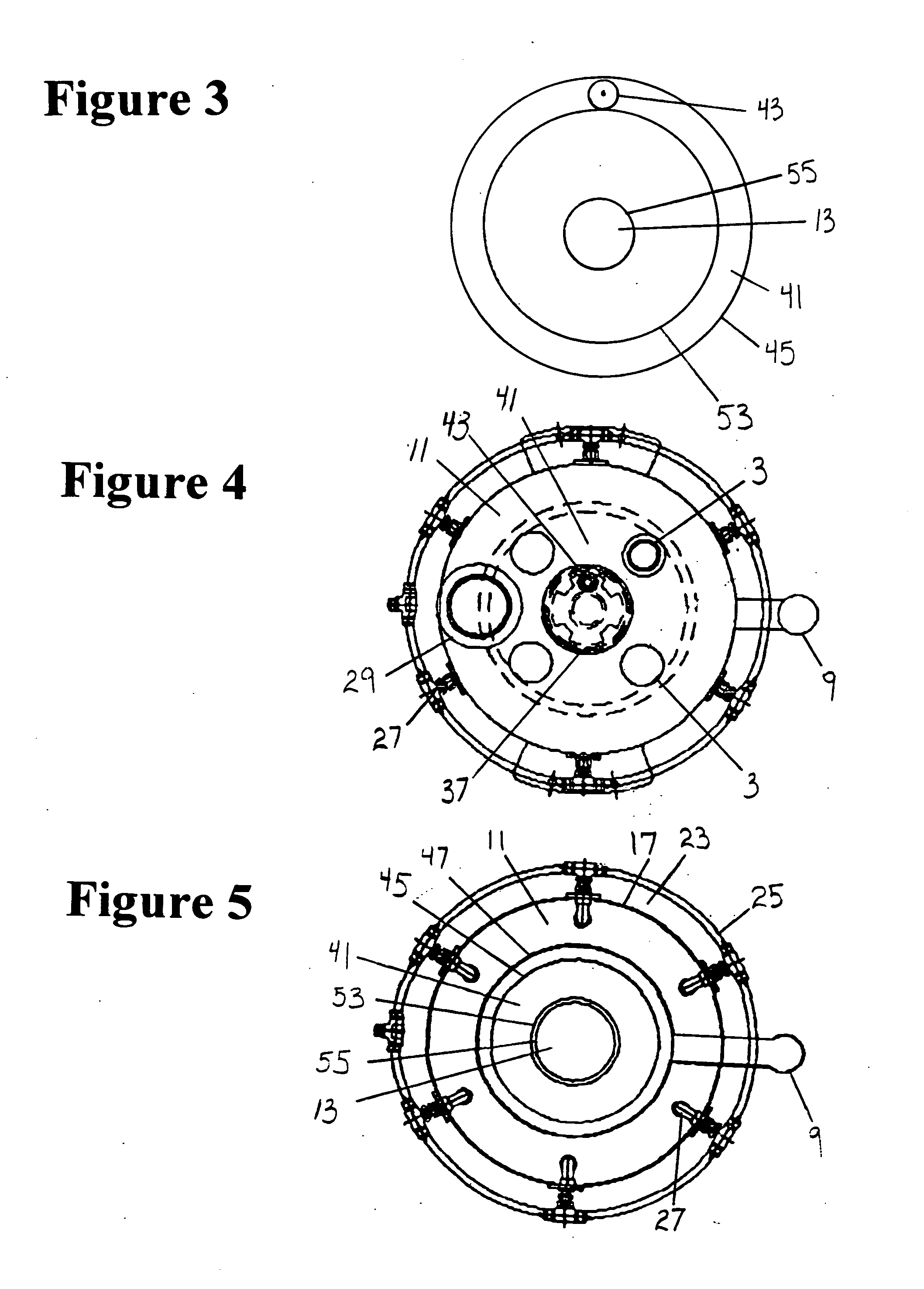
[0021]FIG. 1 is a side cross sectional view of the hazardous gas abatement system 1. Contaminated gases that are in need of neutralization and pacification are taken from a process stream. The contaminated gases feed into the hazardous gas abatement system 1 through a top flow hazardous gas inlet 3. The hazardous gas inlet 3 introduces the contaminated gases through an entry point 5 that is attached to a heater compartment 7. In order to carry out the neutralization and pacification of the contaminated gas, the contaminated gas is heated to temperatures of approximately 1100 C.

[0022] An air inlet 9 introduces an air stream into the clea...


PUM

PropertyMeasurementUnit
Lengthaaaaaaaaaa
Reactivityaaaaaaaaaa

Abstract

A hazardous gas abatement system decontaminates an exit gas stream containing global warming gases using an electrical heater and a water scrubber. One or more top flow hazardous gas inlets introduce hazardous gases into a heater compartment. Air or oxygen is introduced into a separate chamber for dynamic oxidation and cooling. The streams are mixed and oxygen reacts with the hazardous gases. Solid particulates from the reaction are removed by a filter in a quick disconnect bottom chamber. Filtered exhaust gases flow upward in an exhaust chamber surrounding the heater compartment and through water spray scrubbers. A cleaning ring mounted on an eccentric rod cleans particles from the outside of the internal heater, and the inside of the external heater. An air cylinder drives the eccentric rod and cleaning ring down and up between the heaters and stores the ring above the gas inlets.

Description

BACKGROUND OF THE INVENTION [0001] The present invention relates to a method and apparatus for hazardous gas abatement and emission control. Contaminated gas is decomposed, cleaned and neutralized. The present invention is particularly useful for global warming gases and other hard to decompose gases. These gases may include perflourocarbons (PFCs), tetraflouromethane (CF4), hexaflouroethane (C2F6) and many other ozone depleting global warming and greenhouse gases. The present system is also useful for decomposing the exit stream of a semiconductor process by removing gases such as arsine (AsH3) or phosphine (PH3). High temperatures are required to clean, neutralize and decompose these types of gases. [0002] Existing systems do not provide adequate heating to effectively cleanse exit gas streams of global warming gases. Previous gas cleaning systems include controlled decomposition / oxidation (CDO) and others. These previous systems suffered from low efficiency in performance and con...

Claims


Application Information

Patent Timeline
IPC IPC(8): B01D53/34B01D53/70
CPCB01D53/005B01D53/70B01D2251/102B01D2251/11Y02C20/30B01D2257/2064B01D2257/2066B01D2257/553B01D2258/0216B01D2252/103Y10S588/90B01D53/34
Inventor SHIBAN, SAMIR S.
Owner INNOVATIVE ENG SOLUTIONS
Why Eureka
Try Eureka