Method and device for holding a metallic component to be connected, especially a gas turbine blade

a technology for gas turbine blades and metallic components, applied in metal-working holders, soldering auxiliary devices, supports, etc., can solve problems such as damage, and achieve the effects of reducing porosity, reducing density, and reducing porosity

Inactive Publication Date: 2005-09-22
MTU AERO ENGINES GMBH
View PDF4 Cites 22 Cited by
  • Summary
  • Abstract
  • Description
  • Claims
  • Application Information

AI Technical Summary

Benefits of technology

[0005] One advantage of the method according to the invention for holding a metallic component which is to be connected is that the component is held areally, rather than in punctiform fashion, and consequently there is no punctiform loading of its surface. The foam structure, which is dimensionally stable after cooling to ambient temperature, nestles virtually completely against the surface of the component to be connected and represents play-free, rigid, positively locking coupling to the component directly or between the case, the foam structure and the component. The surface or outer skin of the foam is so homogenous and compact that there is no damage to the surface of the component to be connected. Otherwise, the foam structure is cellular and has a porosity. For the component to be connected to further components by 
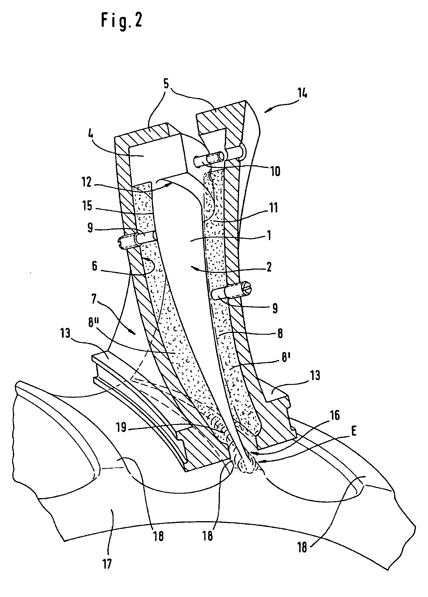
welding or other suitable joining processes, therefore, it is possible for considerable forces to be introduced via the component, for example for pressing the joining surfaces together, without the surface of the component being damaged, the shape of the component being changed or additional large-volume formations having to be provided on the component for introduction of forces and then having to be removed again following the joining operation.
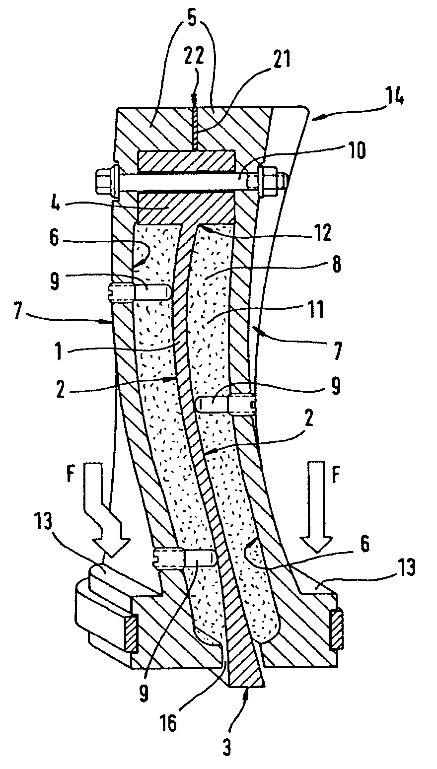
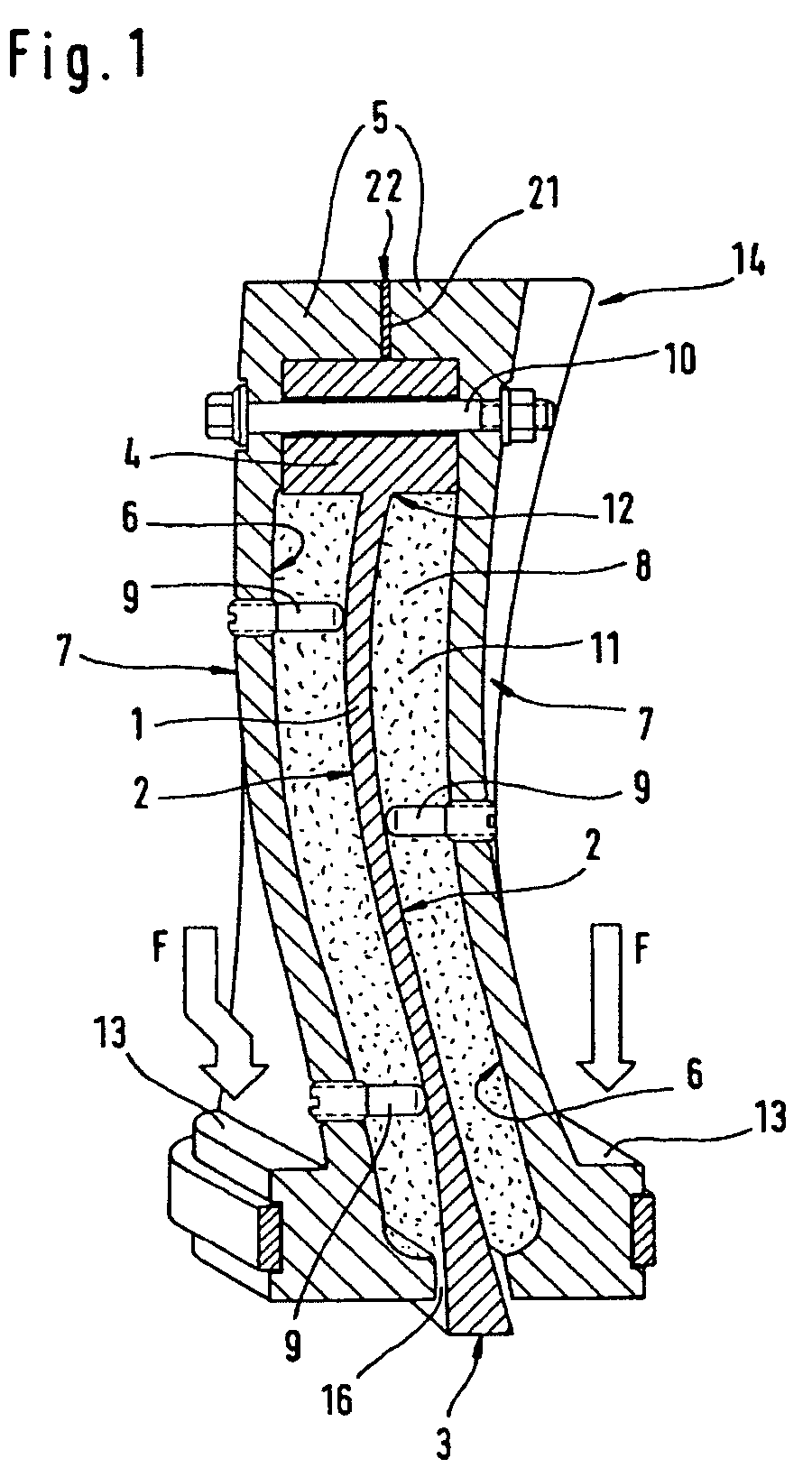
[0011] A releasable spacer element, preferably also made from steel, can be provided in the parting join between the parts of the case, in order to vary the volume in the case, so as to compensate for any shrinkage of the foam during cooling. The spacer element can be removed after cooling. Then, the parts of the case are fixed together, directly abutting one another, so as to reduce the volume around the component, and any shrinkage is compensated for, producing a rigid coupling between case, foam structure and component.
[0013] Depending on the strengths and moduli of elasticity required in the subsequent joining operation, the foamable material used may be a plastic, such as for example polystyrene or polyurethane (PS or PUR), or a metal, such as for example Al or Mg or Ni or Fe or an alloy of these elements, individually in combination, in order to produce the foam structure. The strength and the modulus of elasticity of the foam structure which holds the component is dependent not only on the base material but also on the pore structure and generally rises approximately linearly with the apparent density. The parameters used for foaming of said base materials are matched to the particular application in a manner with which the person skilled in the art will be familiar. The surface or outer skin of the foam structure is closed, compact and not too rough, in order to protect the surface of the component.
[0016] The more base material is locally present in the semifinished product compared to blowing agent, the higher the density after the foaming step, and consequently the lower the porosity of the foam structure. Since the compressive strength of the foam structure is approximately proportional to its density, it is possible to produce foam structures with variable compressive strengths. The foam structure which holds the component may have a lower porosity and therefore a higher density and a greater compressive strength at locations of the component which are subject to high forces during the further machining than at other locations.
[0017] For a foam structure with a high density, the semifinished product has to contain a large proportion of, for example, metallic base material compared to the blowing agent. As the person skilled in the art will understand, the density of the foam structure can also be controlled by means of the ratio of the volume of the semifinished product to the closed volume for the foamable material in the case. A greater degree of play when the closed volume is being filled with the semifinished product leads to a greater porosity and therefore a lower density and a lower compressive strength. The semifinished product may be formed or cut from a large-area metal sheet in a manner which is matched to the shape and size of the closed volume. For a closed volume, it is possible to combine a plurality of semifinished products with different ratios of base material to blowing agent, so that it is possible to produce a locally different porous and therefore dense foam structure.
[0023] The main blade or vane part, for example after it has been cast or forged, may be provided such that it has at least one pin which projects coaxially with respect to its stacking axis from its main blade or vane tip and / or its main blade or vane root beyond the main blade or vane part. The pin may be formed with a circular cross section which is flattened in parts, in order, during positioning of the main blade or vane part in the case or following the formation of the foam structure during positioning of the main blade or vane part in a machining apparatus or machine, to prevent twisting about the stacking axis.

Problems solved by technology

Such damage may occur during the connecting operation, for example when the main blade or vane part is being held by means of clamping jaws, as a result of the punctiform introduction of forces, and is particularly critical if relatively high levels of forces are introduced.

Method used


Image

  • Method and device for holding a metallic component to be connected, especially a gas turbine blade
  • Method and device for holding a metallic component to be connected, especially a gas turbine blade
  • Method and device for holding a metallic component to be connected, especially a gas turbine blade

Examples


Embodiment Construction

[0034]FIG. 1 shows a sectional, perspective illustration of a metallic component 1 which is held, using the method for holding a metallic component, in a corresponding holding apparatus denoted overall by 14. In the present configuration of the method, the metallic component is a main blade or vane part 1 made from a titanium alloy which is used, for example, for a compressor of a gas turbine. The main blade or vane part 1 has an outer surface 2 and a joining surface 3, which is connected to a joining surface of a further component (not shown in FIG. 1). In the present configuration, the main blade or vane part 1 additionally has an attachment 4, by means of which the main blade or vane part 1 is fixed for accurate positioning in the holding apparatus 14.

[0035] As an alternative, the attachment 4 may also be dispensed with or designed as a flattened pin 19 as illustrated in FIG. 4. The pin 19 runs coaxially with respect to the stacking axis 20 of the main blade or vane part 1. The ...


PUM

PropertyMeasurementUnit
metallicaaaaaaaaaa
volumeaaaaaaaaaa
foamableaaaaaaaaaa

Abstract

A method for holding a metallic component of a gas turbine, which is to be connected, includes providing a metallic component having a surface and at least one machining or joining surface, providing a case having a cutout, which has an inner surface, for receiving the component, positioning the component in the case in such a manner that its surface is surrounded, at a distance, by the inner surface of the case, so as to form a closed volume and so that its machining or joining surface does not face the volume, filling the volume with a foamable material, foaming the material and cooling so as to form a dimensionally stable foam, structure. An apparatus for holding the metallic component and a method for connecting the metallic component to a further component are also provided.

Description

BACKGROUND AND SUMMARY OF THE INVENTION [0001] This invention relates to a method and an apparatus for holding a metallic component which is to be connected, in particular a main blade or vane part for a gas turbine, and to a method for connecting a metallic component, in particular a main blade or vane part for a gas turbine, to a further component. [0002] It is generally desirable that metallic components or surfaces thereof should not be damaged or adversely affected in any way when they are being connected to further components. For example, if a main blade or vane part of a stationary gas turbine or of an aircraft engine is being connected to a blade or vane root, a blade or vane cover strip or a carrier of a compressor or turbine rotor by means of a suitable method, for example welding, the shape and surface of the main blade or vane part should not be adversely affected in terms of aerodynamic or strength aspects. Such damage may occur during the connecting operation, for exa...

Claims


Application Information

Patent Timeline
Patent Type & Authority Applications(United States)
IPC IPC(8): B23K20/12B23P15/00B23Q3/08B23Q3/18B23Q16/00B25B5/14F01D5/14F01D5/28
CPCB23K20/1205B23K2201/001B23P15/006B23Q3/063B23Q3/086Y02T50/673B23Q16/00B25B5/14F01D5/147F01D5/282B23Q3/18B23K2101/001Y02T50/60
Inventor MEIER, REINHOLD
Owner MTU AERO ENGINES GMBH
Why Eureka
Try Eureka