Sequential lithographic methods to reduce stacking fault nucleation sites and structures having reduced stacking fault nucleation sites

a stacking fault and nucleation site technology, applied in the direction of chemically reactive gases, crystal growth process, chemistry apparatus and processes, etc., can solve the problems of difficult to grow into large single crystals, difficult to produce silicon carbide, and high melting point of silicon carbid

Active Publication Date: 2005-09-22
CREE INC
View PDF17 Cites 19 Cited by
  • Summary
  • Abstract
  • Description
  • Claims
  • Application Information

AI Technical Summary

Benefits of technology

[0039] Moreover, methods and structures according to other embodiments of the present invention may use

Problems solved by technology

Silicon carbide has an extremely high melting point and is one of the hardest known materials in the world.
Because of its physical properties, however, silicon carbide also may be relatively difficult to produce.
Because silicon carbide can grow in many polytypes, it may be difficult to grow into large single crystals.
The high temperatures used to grow silicon carbide also may make control of impurity levels (including doping) relatively difficult, and likewise may raise difficulties in the production of thin films (e.g. epitaxial layers).
Because of its hardness, the traditional steps of slicing and polishing semiconductor wafers also may be more difficult with silicon carbide.
Similarly, its resistance to chemical attack may make it difficult to etch in a conventional fashion.
As a result, growing single crystal substrates and high quality epitaxial layers (“epilayers”) in silicon carbide has been, and may remain, a difficult task.
This increase is generally referred to as “Vf drift.” For a number of reasons, such functional problems in semiconductor devices can often result from defects in the crystal structure of the material from which the devices are formed.
However, the presence of crystalline defects in silicon carbide films may limit the performance of electronic devices fabricated in the films, depending on the type, location, and density of the defects.
Certain defects, such as micropipes, are known to severely limit and even prevent dev

Method used


Image

  • Sequential lithographic methods to reduce stacking fault nucleation sites and structures having reduced stacking fault nucleation sites
  • Sequential lithographic methods to reduce stacking fault nucleation sites and structures having reduced stacking fault nucleation sites
  • Sequential lithographic methods to reduce stacking fault nucleation sites and structures having reduced stacking fault nucleation sites

Examples


Embodiment Construction

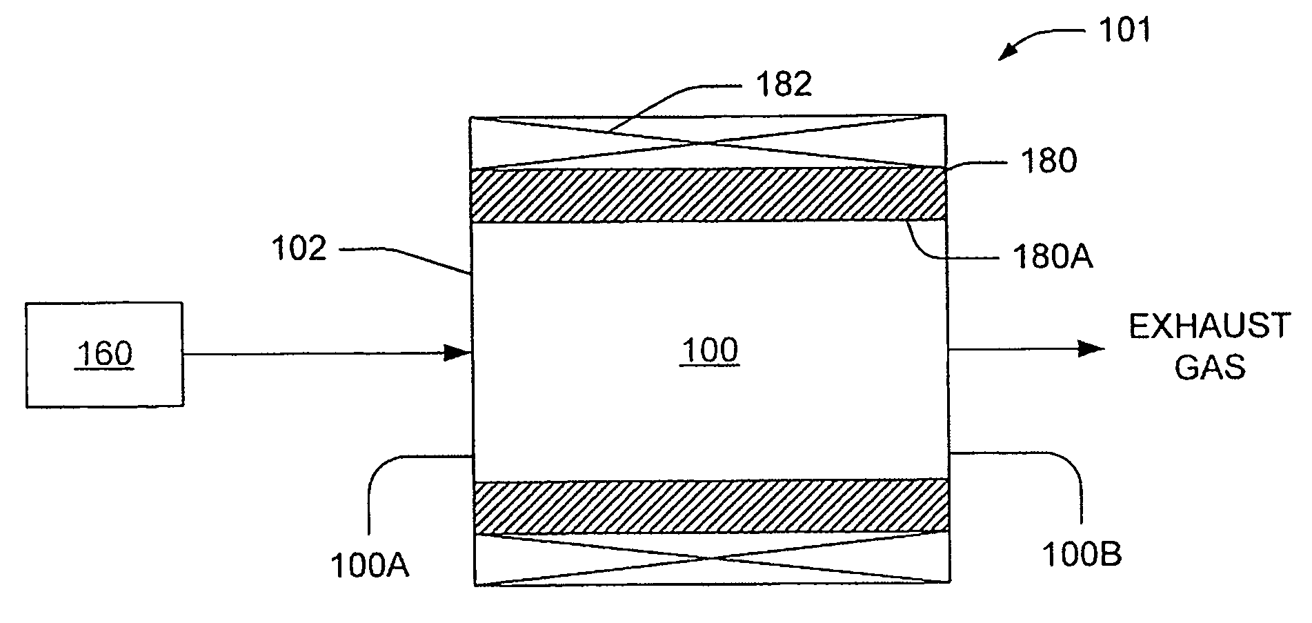
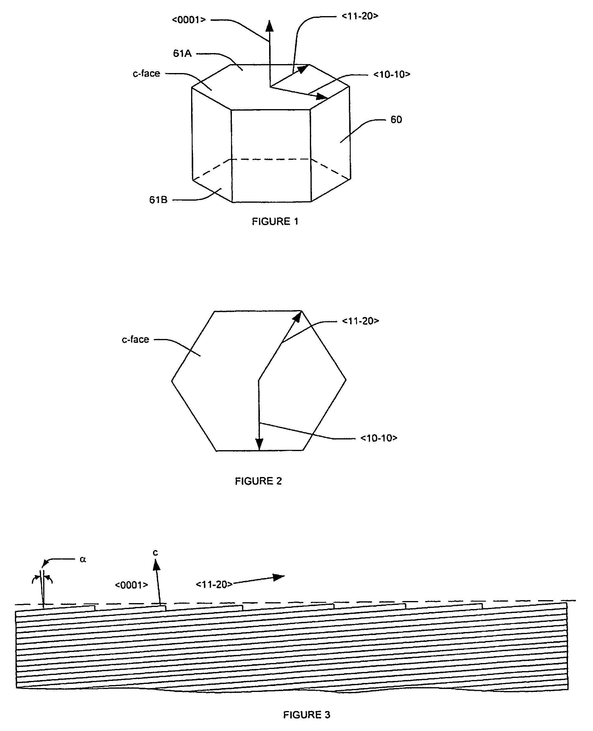
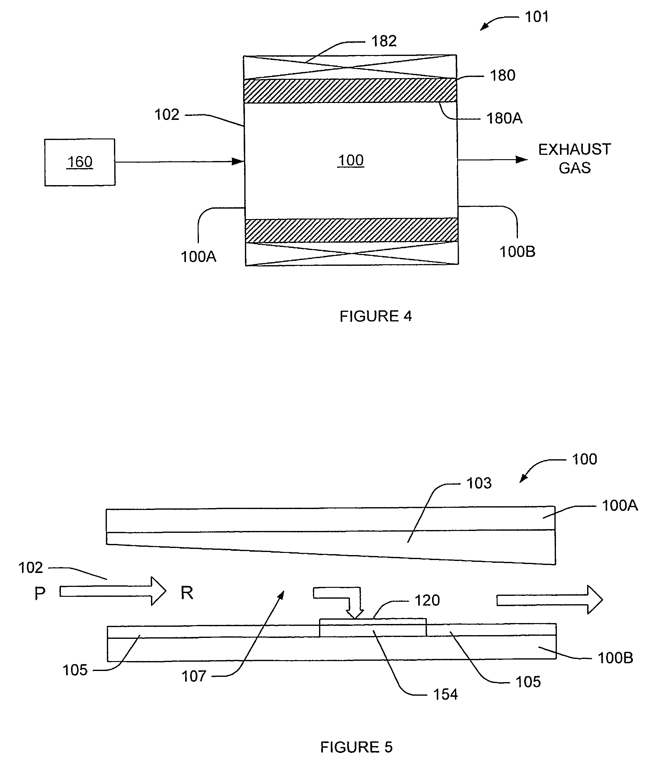
[0059] The present invention now will be described more fully hereinafter with reference to the accompanying drawings, in which embodiments of the invention are shown. This invention may, however, be embodied in many different forms and should not be construed as limited to the embodiments set forth herein. Rather, these embodiments are provided so that this disclosure will be thorough and complete, and will fully convey the scope of the invention to those skilled in the art. In the drawings, the size and relative sizes of layers and regions may be exaggerated for clarity. It will be understood that when an element or layer is referred to as being “on” another element or layer, it can be directly on the other element or layer or intervening elements or layers may be present. In contrast, when an element is referred to as being “directly on” another element or layer, there are no intervening elements or layers present. Like numbers refer to like elements throughout. As used herein, t...


PUM


Abstract

An epitaxial silicon carbide layer is fabricated by forming first features in a surface of a silicon carbide substrate having an off-axis orientation toward a crystallographic direction. The first features include at least one sidewall that is orientated nonparallel (i.e., oblique or perpendicular) to the crystallographic direction. A first epitaxial silicon carbide layer is then grown on the surface of the silicon carbide substrate that includes first features therein. Second features are then formed in the first epitaxial layer. The second features include at least one sidewall that is oriented nonparallel to the crystallographic direction. A second epitaxial silicon carbide layer is then grown on the surface of the first epitaxial silicon carbide layer that includes the second features therein.

Description

CROSS-REFERENCE TO PROVISIONAL APPLICATION [0001] This application claims the benefit of and priority from Provisional Application Ser. No. 60 / 554,123, filed Mar. 18, 2004, entitled Lithographic Method to Reduce Stacking Fault Nucleation Sites and Reduce Vf Drift in Bipolar Devices and Structures Having Reduced Stacking Fault Nucleation Sites, the disclosure of which is hereby incorporated herein by reference in its entirety as if set forth fully herein.STATEMENT OF GOVERNMENT INTEREST [0002] This invention was developed under government contract No. N00014-02-C-0302. The U.S. Government has a paid-up license in this invention and the right in limited circumstances to require the patent owner to license others on reasonable terms as provided for by the terms of contract No. N00014-02-C-0302 awarded by the Defense Advanced Research Projects Agency (“DARPA”).FIELD OF THE INVENTION [0003] This invention relates to semiconductor materials and devices and fabrication methods therefor, an...

Claims


Application Information

Patent Timeline
IPC IPC(8): H01L21/04H01L21/20H01L21/205
CPCY10S438/931H01L21/02378H01L21/02639H01L21/02433H01L21/02529H01L21/0243C30B25/02
Inventor HALLIN, CHRISTERLENDENMANN, HEINZSUMAKERIS, JOSEPH JOHN
Owner CREE INC
Why Eureka
Try Eureka