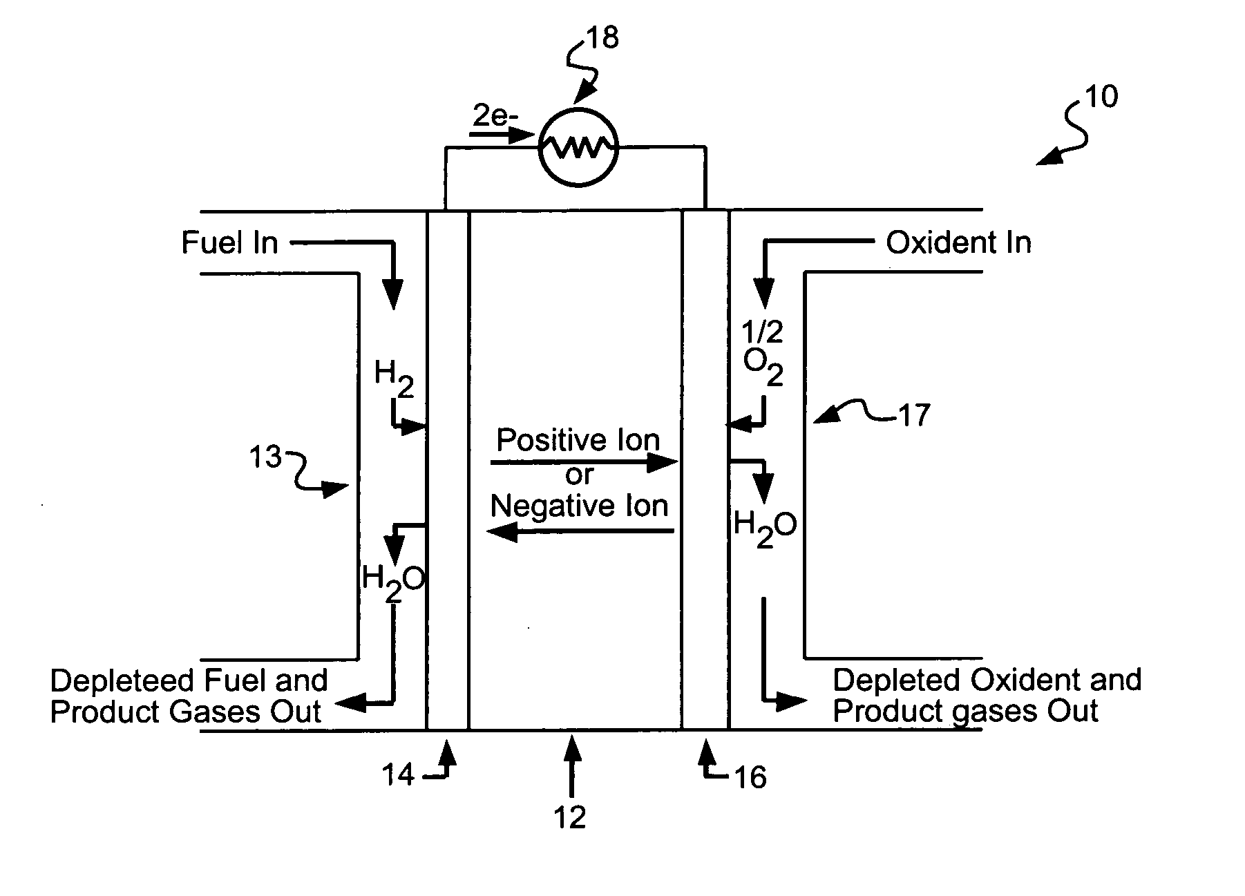
Fuel cell

a fuel cell and anode technology, applied in the field of fuel cells, can solve the problems of high cost, low efficiency, and low utilization rate of fuel cells, and achieve the effects of facilitating hydrogen consumption, high catalytic material, and high cos

Inactive Publication Date: 2005-09-22
OVONIC BATTERY CO INC
View PDF18 Cites 5 Cited by
  • Summary
  • Abstract
  • Description
  • Claims
  • Application Information

AI Technical Summary

Benefits of technology

[0009] An objective of the present invention is an inexpensive, highly catalytic material that may be used for facilitating hydrogen consumption in a fuel cell anode. Another objective of the present invention is a catalytic material having a finely divided metal particulate with very small particle size. Yet another objective of the present invention is a cost effect method for making the instant catalytic materials. Yet another objective of the present invention is a fuel cell anode and a fuel cell incorporating the instant catalytic materials.

Problems solved by technology

Despite their potential advantages, fuel cells have not been widely utilized due in large part to their relatively high cost.
An important factor contributing to this high cost is the catalytic inefficiencies of the prior art catalytic materials and / or the high costs of many of these materials.
The catalytic inefficiencies of the materials increase the operating costs of the fuel cell since such inefficiencies result in a lower electrical energy output for a given amount of fuel.
The use of expensive catalytic materials, such as noble metal catalysts, results in fuel cells which are too expensive for widespread application.
Prior art fuel cell anode catalysts, which have been generally predicated on either expensive noble metal catalysts with a relatively low density of catalytically active sites, have not been able to meet the requirements.

Method used


Image

  • Fuel cell
  • Fuel cell
  • Fuel cell

Examples


example 1

[0093] In this example, a nickel metal hydride (NiMH) rechargeable battery is chosen as the test bed to demonstrate the capability of hydrogen gas absorption of the current invention in a hostile gas environment. Raw materials with purity higher than 99% were mixed and loaded in a vacuum induction furnace, melted, and poured into a steel mold. The ingot was pulverized into a 200-mesh powder and compacted onto a metal substrate to form an electrode belt. The electrode was used as the negative electrode in conjunction with nickel hydroxide positive electrodes, separators, and a 30% KOH electrolyte to fabricate typical sealed NiMH rechargeable batteries.

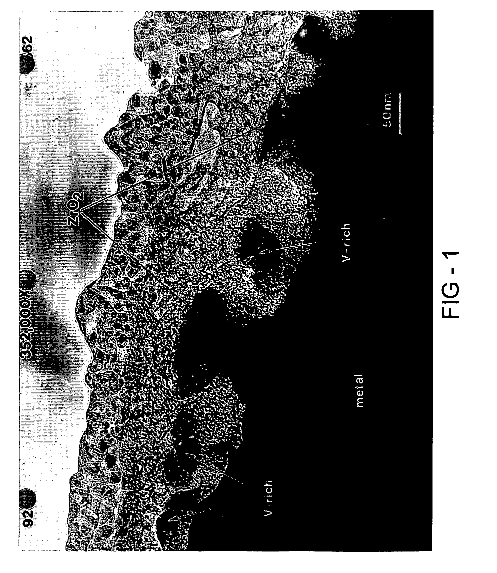
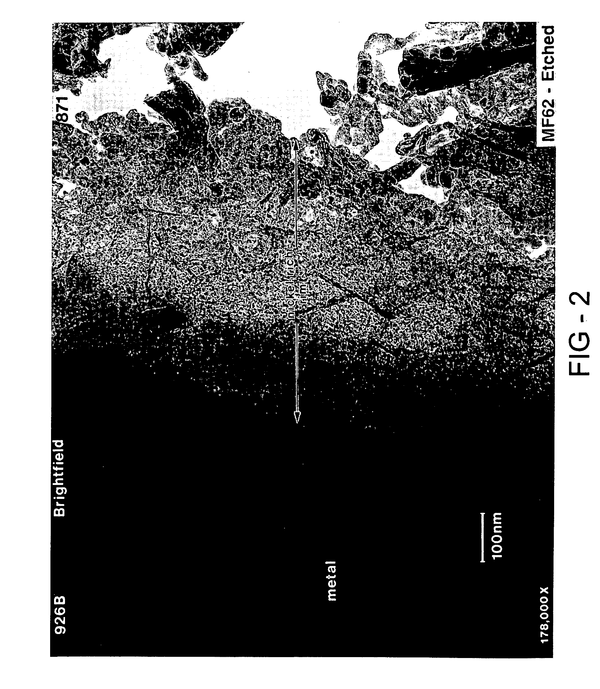
[0094] The hydrogen storage alloy was activated under a heat treatment of 60° C. for five days. The surface of the activated alloy comprises a metal particulate embedded in a porous metal oxide. The oxide prevents further oxidation of the alloy and the porosity in the oxide make it possible for both gas and electrolyte to penetrate. Th...

example 2

[0097] An identical NiMH battery as used in Example 1 was charged and discharged 500 times. The heavily cycled battery was then charged under C / 10 rate for 20 hours. The cell voltage and pressure were monitored during the entire charge process (FIG. 9). As shown in FIG. 9, the cell pressure increased from 0 PSI to 150 PSI. A small sample of gas was withdrawn from the cell and the gas content determined by gas chromatography (GC) was 96.3% H2, 0.4% O2, and 3.3% N2. After the cell was charged to 200% of its rated capacity, it was left idle in the open-circuit configuration for five hours. The cell voltage and pressure were monitored during this open circuit period (FIG. 10). The cell pressure decreased from 150 PSI to less than 80 PSI in about five hours demonstrating that, even after 315 cycles, the alloy surface was still able to act as a catalyst effective to decompose hydrogen gas into atomic hydrogen which could then be absorbed into the bulk of the hydrogen storage alloy materia...


PUM

PropertyMeasurementUnit
timeaaaaaaaaaa
timeaaaaaaaaaa
temperatureaaaaaaaaaa

Abstract

A fuel cell. The anode of the fuel cell comprises a hydrogen oxidation catalyst comprising a finely divided metal particulate. The metal particulate may be a nickel and / or nickel alloy particulate having a particle size less than about 100 Angstroms.

Description

RELATED APPLICATION INFORMATION [0001] This application is a divisional application of U.S. patent application Ser. No. 09 / 523,820 filed on Mar. 13, 2000, which is a continuation-in-part of U.S. patent application Ser. No. 09 / 290,633 filed on Apr. 12, 1999. U.S. patent application Ser. No. 09 / 523,820 is hereby incorporated by reference herein.FIELD OF THE INVENTION [0002] The present invention relates to fuel cells and more specifically to fuel cell anodes. BACKGROUND OF THE INVENTION [0003] A fuel cell is an electrochemical device in which the chemical energy of a conventional fuel is converted directly and efficiently into low voltage electrical energy. Fuel cells have many potential applications such as supplying power for transportation vehicles, replacing steam turbines and remote power supply applications. [0004] Fuel cells, like conventional batteries, operate by utilizing electrochemical reactions. Unlike a battery, in which chemical energy is stored within the cell, fuel ce...

Claims


Application Information

Patent Timeline
Patent Type & Authority Applications(United States)
IPC IPC(8): B01J23/755B01J23/76B22F1/00B01J23/889B01J35/02B01J35/10B01J37/06B22F1/02B22F5/00C01B3/00C22C14/00C22C16/00C22C19/00C22C27/02C22C27/06H01M4/38H01M4/86H01M4/88H01M4/90H01M8/08H01M8/10
CPCB01J23/755Y02E60/321B01J25/00B01J25/02B01J35/023B01J35/10B01J37/0018B01J37/06C01B3/001C01B3/0031C01B3/0078C22C14/00C22C16/00C22C27/025C22C27/06H01M4/383H01M4/8605H01M4/8652H01M4/90H01M4/9041H01M4/9075H01M4/9083H01M4/921H01M8/04208H01M8/08H01M8/083H01M10/345H01M2004/8684H01M2008/1095Y02E60/327Y02E60/50F17C11/005B01J23/76Y02E60/32Y02P70/50Y02E60/10B01J35/60B01J35/40
Inventor FETCENKO, MICHAEL A.OVSHINSKY, STANFORD R.YOUNG, KWO
Owner OVONIC BATTERY CO INC
Why Eureka
Try Eureka