
Micro-protruding structure

a micro-protruding structure and micro-protruding technology, applied in the direction of separation processes, instruments, filtration separation, etc., can solve the problems of poor angular precision, poor positional precision, and inability to fully satisfy the characteristics of the micro-protruding structure required by the above fabrication method, so as to improve resolution, high positional precision, and improve the effect of resolution

Inactive Publication Date: 2005-09-29
SII NANOTECHNOLOGY INC
View PDF3 Cites 5 Cited by
  • Summary
  • Abstract
  • Description
  • Claims
  • Application Information

AI Technical Summary

Benefits of technology

[0029] The linear material of the micro-protruding structure is used as a probe of the scanning probe microscope. To precisely bring the linear material to a position of measurement, the linear material must have been provided at the end of the probe portion maintaining a high positional precision. To observe a sample which is conspicuously rugged, it is necessary that the micro-protruding structure having a high aspect ratio must have been provided perpendicularly to the surface of the sample. By providing the micro-protruding structure of the present invention, it becomes possible to properly control the position for mounting the linear material having a high aspect ratio and the direction thereof (to so constitute that the end of the probe portion is perpendicular to the sample surface).
[0030] The micro-protruding structure having hole structures of a small size and provided with fine linear materials, becomes small in size, i.e., of the order of microns or smaller. It is, therefore, made possible to easily realize the micro-protruding structure for a scanning probe microscope that is to be used in tiny regions.
[0031] By using carbon nano-tubes or metal whiskers as the linear materials, the volume effect at the end decreases, the shape is measured maintaining an improved resolution, physical properties are measured maintaining an improved resolution, and the shape at the end of the probe is deteriorated less as compared to those of the probe (micro-protruding structure having a small aspect ratio obtained by machining a semiconductor wafer relying upon the photolithography technology) used in the currently employed scanning probe microscopes.

Problems solved by technology

However, the above fabrication methods are not capable of fully satisfying the characteristics required for the micro-protruding structure.
However, since the observation is from one direction only, the direction in which the linear material protrudes is not determined, and the angular precision is poor (see, for example, a patent document 2).
When the micro-protruding structure is to be constituted by dispersing the catalyst on the mother member on the lever to grow the linear material, the positional precision is poor since it is difficult to mount the catalyst of about several tens to several namometers on a desired position maintaining a high positional precision.
Besides, since the direction of growth is not definite, the micro-protruding structure cannot be constituted by the linear material that is controlled at a desired angle (direction).
As described above, the conventional protruding structure is not capable of satisfying all of the positional precision at a position where the linear material of the end portion is provided, angular (directional) precision, thickness and aspect ratio.
It is therefore difficult to so fabricate the micro-protruding structure as to accomplish a desired angle.
Besides, since each micro-protruding structure is fabricated by hand by using a manipulator, the productivity is low.
When the micro-protruding structure is to be constituted by using a material for growing the linear material, it is difficult to mount, on a desired position, the material that is to be grown by about several tens to several namometers.
Besides, the direction of growth is not definite.
It is not, therefore, possible to constitute the micro-protruding structure maintaining a desired positional precision by using the linear material of which the direction is controlled.

Method used


Image

  • Micro-protruding structure
  • Micro-protruding structure
  • Micro-protruding structure

Examples


embodiment 1

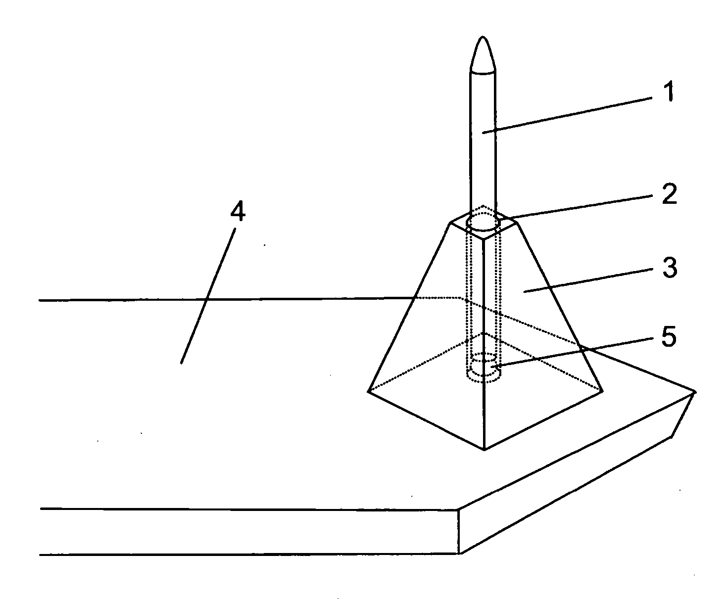
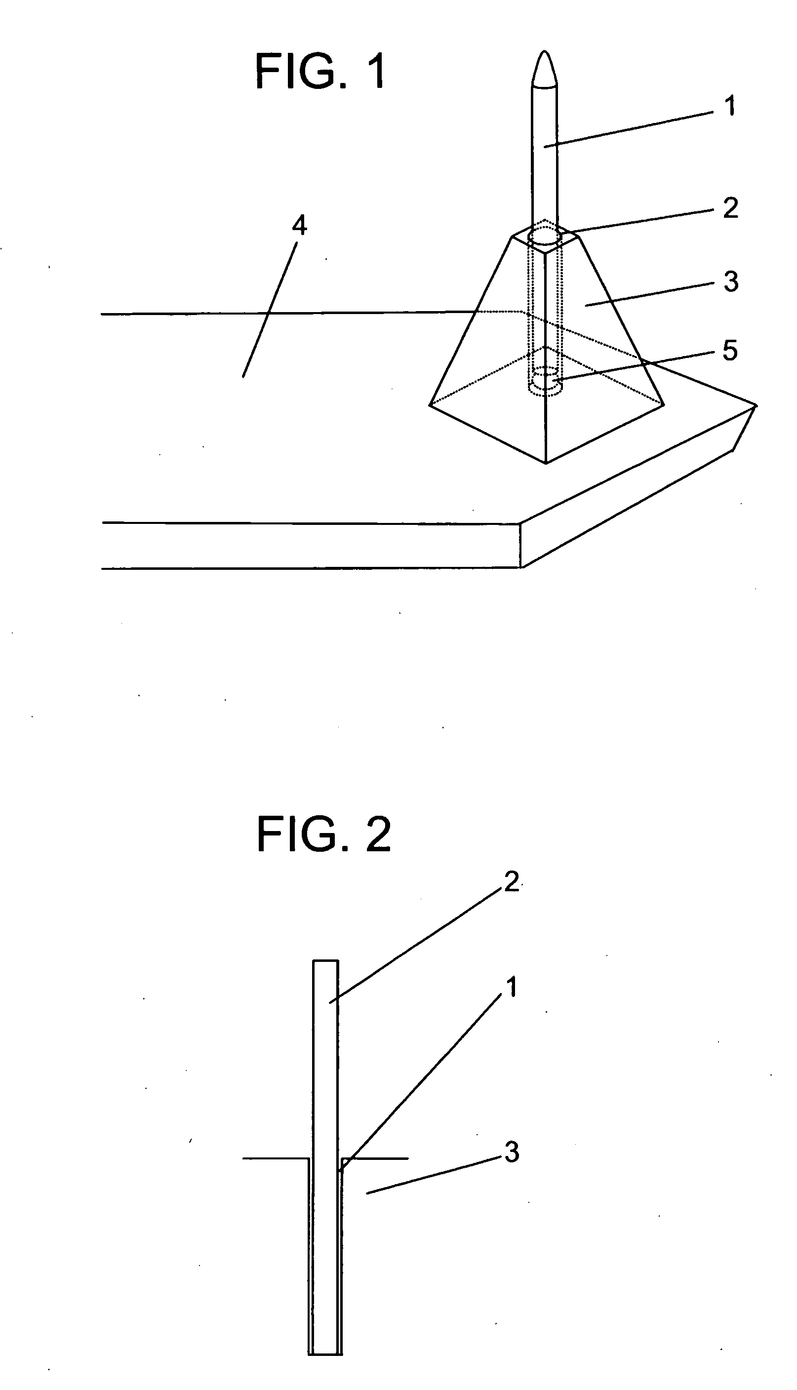
[0037]FIG. 1 is a view schematically illustrating the constitution of a micro-protruding structure according to a first embodiment of the invention provided on a cantilever of a scanning probe microscope. In FIG. 1, reference numeral 4 denotes a cantilever (cantilevered beam-type leaf spring) of a scanning probe microscope. At an end of the cantilever 4, there is formed a mother member 3 of a probe portion of the shape of a square truncated cone having a bottom side of about 10 μm. A fine hole structure 1 of a diameter of several tens of nanometers is formed in the central portion of the mother member 3 of the probe portion reaching from the upper surface to the bottom surface thereof nearly at right angles with the surface of the mother member 3 of the probe portion of the cantilever 4. A fine linear material 2 having an aspect ratio of not smaller than 10 is provided in the hole structure 1 so as to protrude outward from the bottom surface of the hole structure 1. The angular dire...

embodiment 2

[0041]FIG. 2 is a view schematically illustrating the micro-protruding structure according to a second embodiment of the invention. As an electron-emitting electrode, a linear material 2 of carbon nano-tube is inserted in the hole structure 1 provided vertically to the mother member 3 of the substrate. The hole structure 1 can be formed to in alignment with the center axis of the electron lens. The emission of electrons is homogeneously affected by an electric field, and the aberration of the electron beam is suppressed.

embodiment 3

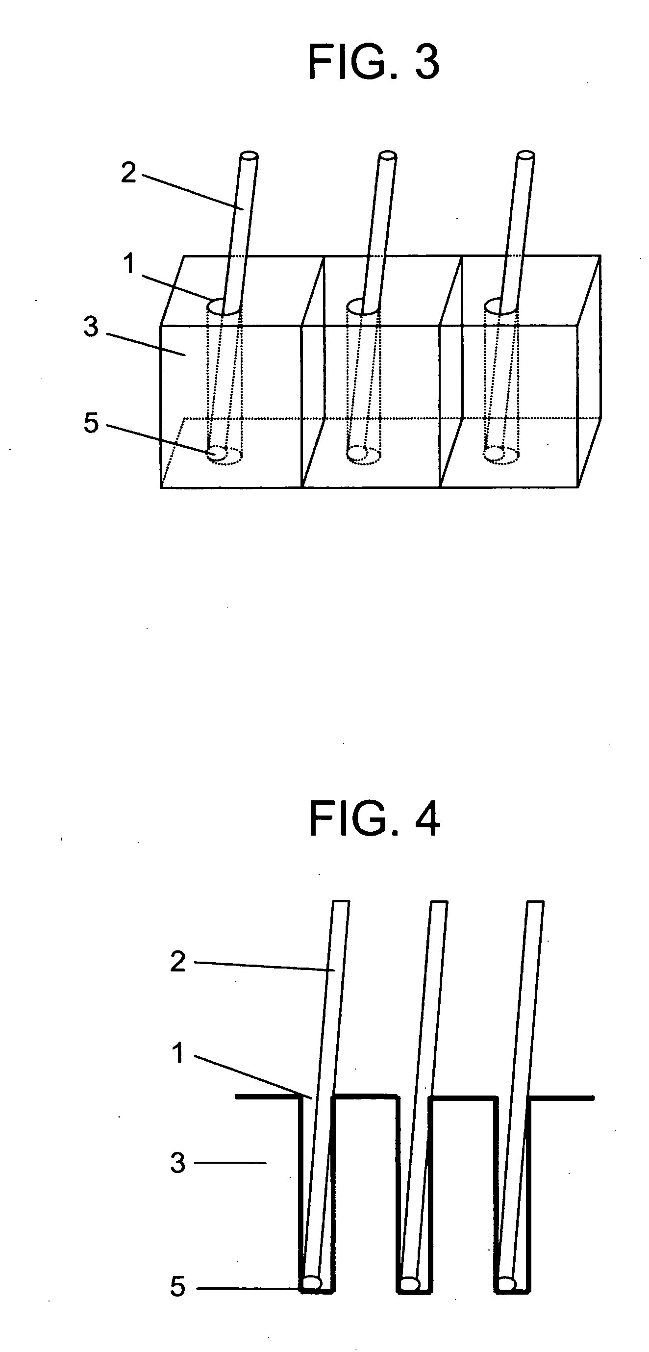
[0042]FIG. 3 is a view schematically illustrating the micro-protruding structure according to a third embodiment of the invention. FIG. 4 is a sectional view of the micro-protruding structure illustrated in FIG. 3. As electron-emitting electrodes, there are formed a plurality of micro-protruding structures to emit large amounts of electrons so as to be applied to a display element. By adjusting the density of the hole structures 1, the density of emitting electrodes can be controlled. The direction of the linear materials 2 is determined depending upon the angle of the hole structures, and can be constituted to be perpendicular to the electric field to draw out the electron-emitting efficiency to a maximum degree. The catalysts 5 are provided on the bottom surfaces of the hole structures 1, and the linear materials 2 are grown to provide the structure at one time utilizing many hole structures.


PUM


Abstract

A micro-protruding structure which has a high positional precision and an angular (directional) precision, which is made of a linear material having a large aspect ratio, and which is provided for an analyzer, a display device, a machining device, a measuring device and an observation device. The micro-protruding structure is fabricated by growing a linear material of a carbon nano-tube from the bottom of the hole structure perforated by a focused ion beam. This permits a direction from the bottom of the hole structure to the opening to become nearly in alignment with the direction of the linear material that protrudes from the hole structure.

Description

BACKGROUND OF THE INVENTION [0001] 1. Field of the Invention [0002] This invention relates to a micro-protruding structure provided for an analyzer, a display device, a machining device, a measuring device and an observation device. More particularly, the invention relates to a micro-protruding structure provided for a probe portion of a scanning probe microscope, for an electrode portion for emitting electrons, for a probe portion of a micro-chemical chip, for a probe portion for detecting a micro-current of biological tissues, and for a probe portion used for a high-density recording / reproducing apparatus. [0003] 2. Description of the Related Art [0004] In order to observe fine structures on the surfaces of samples on a nanometer scale, the scanning probe microscope has heretofore been using a probe portion having a micro-protruding structure at an end thereof for scanning the surfaces of the samples and is provided with a sharp probe having an end portion of a diameter of not lar...

Claims


Application Information

Patent Timeline
Patent Type & Authority Applications(United States)
IPC IPC(8): B81B1/00B82B1/00G01Q60/38G01Q70/00G01Q70/10G01Q70/12G01Q70/16H01L29/45
CPCB81B1/008B82Y10/00B82Y15/00H01J2237/3118G01Q70/12G01Q70/16H01J2201/30469B82Y35/00
Inventor SHIGENO, MASATSUGU
Owner SII NANOTECHNOLOGY INC
Learn More